Eureka AIR delivers breakthrough ideas for toughest innovation challenges, trusted by R&D personnel around the world.

Connector assembly having power contacts which comprise a plurality of contact inserting portions

a technology of power contacts and connector assemblies, which is applied in the direction of coupling device details, coupling device connections, electric discharge lamps, etc., can solve the problems of long charge time and long time-consuming for data transfer at 480 mbps between devices

Active Publication Date: 2015-02-24
ADVANCED CONNECTEK INC
View PDF4 Cites 5 Cited by
  • Summary
  • Abstract
  • Description
  • Claims
  • Application Information

AI Technical Summary

Benefits of technology

[0010]The primary objective of the present invention is to provide a connector assembly which is able to increase USB device power charging speed.
[0020]It is to be noted from the objectives of the preferred embodiment of the present invention that the insulative body of the plug has first convex portions formed on two opposite sides of the tongue portion for a specified socket, which prevents the plug of the present invention from connection to an unwanted USB. The invention provides a fool-proofing device to prevent users from plugging the plug in sockets which are not designed for the structure of the present invention. In addition, the socket has a connector metal shield which embosses on the outer surface of the connector metal shield for accommodation of the first convex portion and the second convex portion to connect to the metal shield to provide the connection for the plug and socket.

Problems solved by technology

USB 2 has a maximum speed of 480 Mbps, which was considered adequate at the time of release but is now unsatisfactory due to the large size of multimedia data requiring high storage capacities of 64 GB or greater and the fact that cell phones and PDAs now have large capacity built-in storage, so a full transfer of data at 480 Mbps between devices can take a long time.
In conventional Micro-USB use, a portable device can only draw a small current after digital negotiation with the host or hub, resulting in a long charge time.

Method used


Image

  • Connector assembly having power contacts which comprise a plurality of contact inserting portions
  • Connector assembly having power contacts which comprise a plurality of contact inserting portions
  • Connector assembly having power contacts which comprise a plurality of contact inserting portions

Examples


Embodiment Construction

[0030]The following description is merely exemplary in nature, and is in no way intended to limit the present teachings, applications, or uses. Those of skill in the art will recognize that the following description is merely illustrative of the principles of the invention, which may be applied in various ways to provide many different alternative embodiments.

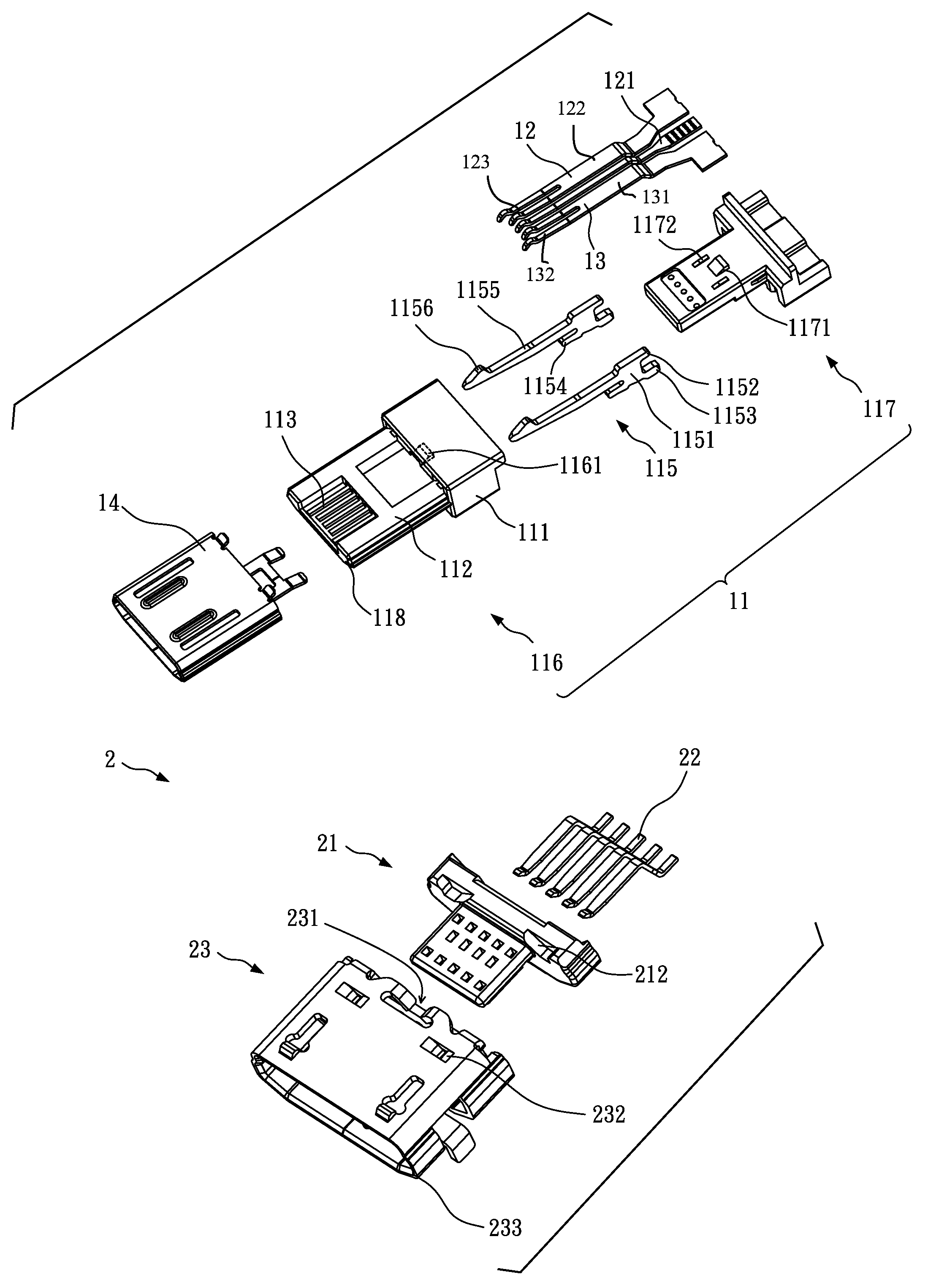
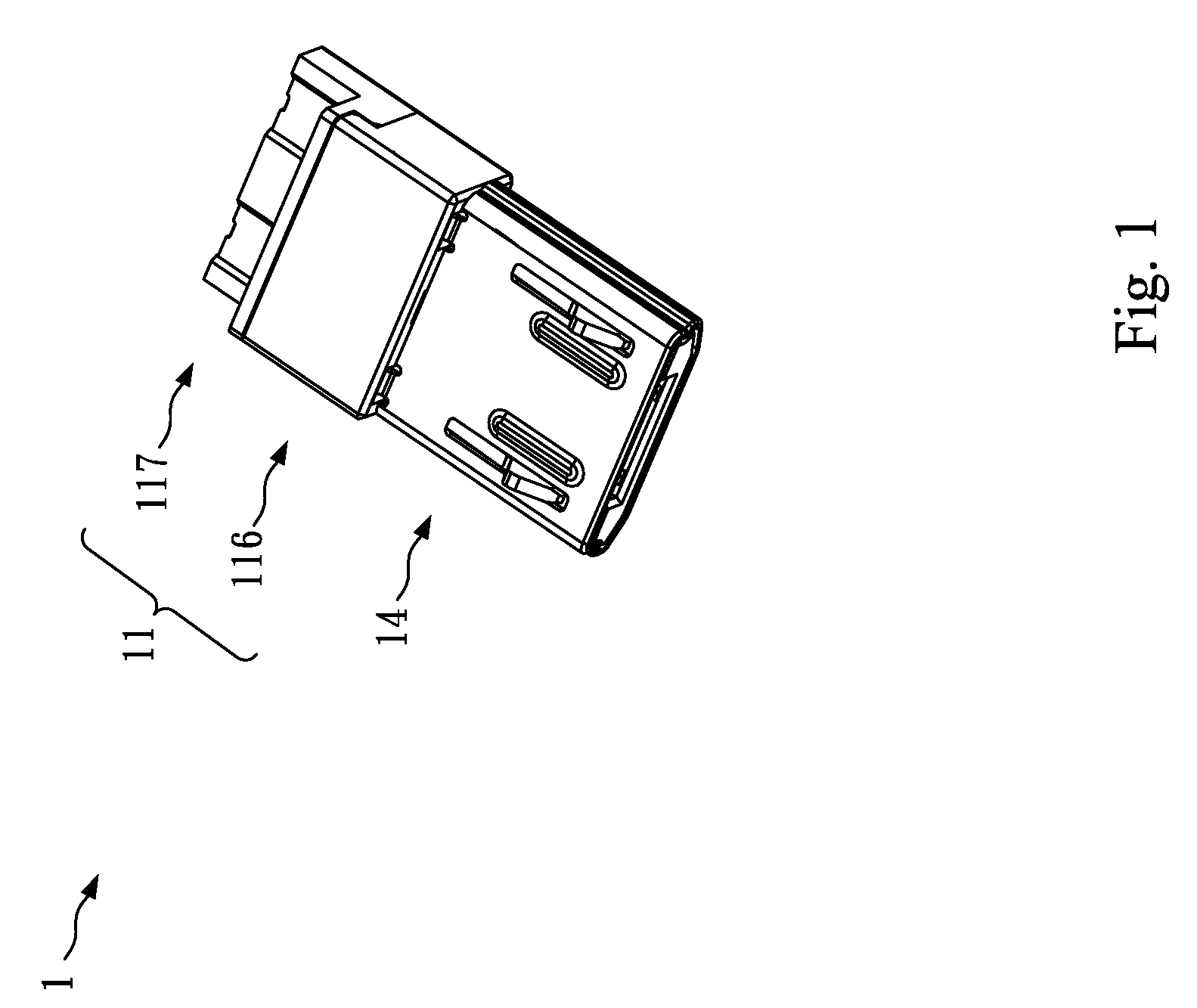
[0031]FIG. 1 is an illustration of a perspective view of the preferred embodiment of the present invention. There is shown the connector assembly has a plug 1, which comprises a metal shield 14 and an insulative body 11 which has a first body portion 116 and a second body portion 117. In the preferred embodiment, the connector is utilized in Micro-USB device.

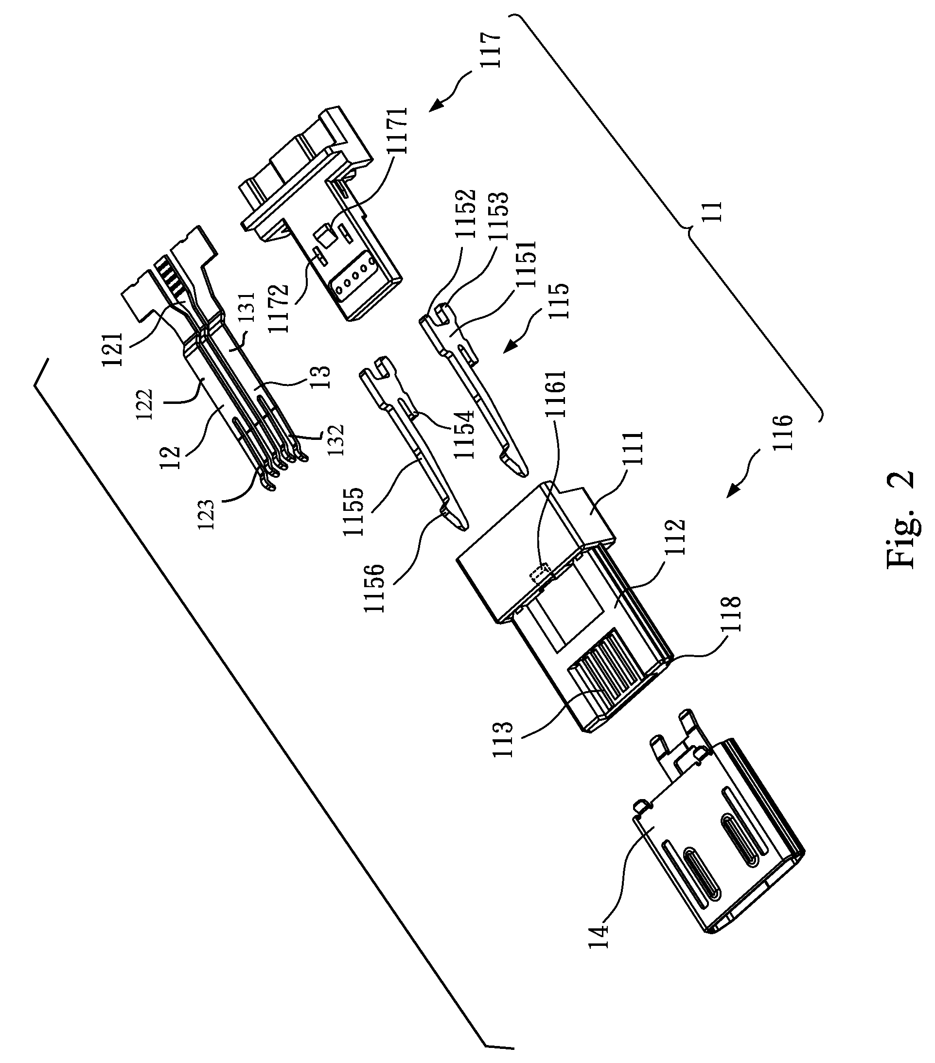
[0032]FIGS. 2 and 3 are illustrations of the preferred embodiment of the present invention that the plug is illustrated in exploded perspective views. The insulative body 11 has a base portion 111 and a tongue portion 112 extending from the base portion 111. The tongue port...


PUM


Abstract

A connector assembly has a plug and socket; the plug includes an insulative body, at least one first power contact, at least one second power contact and a metal shield. The insulative body has a base portion and a tongue portion extending from the base portion. The tongue portion includes a plurality of power contact grooves and penetrates through the base portion, and at least one first convex portion defined in a periphery of the tongue portion. The first power contact and the second power contact are respectively formed on the power contact grooves of the insulative body for connection to a power source in a socket of host device. The metal shield encloses the tongue portion of the insulative body to cover the tongue portion. Consequently, the charging speed can be increased, reducing charging time.

Description

CROSS-REFERENCE TO RELATED APPLICATION[0001]This non-provisional application claims priority under 35 U.S.C. §119(a) on Patent Application No. 201210326696.8 filed in China, P.R.C. on Sep. 6, 2012, the entire contents of which are hereby incorporated by reference.BACKGROUND[0002]1. Technical Field[0003]The invention relates to an electrical connector assembly, more particularly, to a Micro-USB connector assembly.[0004]2. Related Art[0005]Universal Serial Bus (USB) is a serial bus communication standard designed to provide a standard communication port between computer hardware and a host computer. Recently, the marketplace has developed consumer devices applying Universal Serial Bus to most consumer applications. A Universal Serial Bus (“USB”) supports plug and play installation, and its development has increased due to the demand of higher data transmission and stability.[0006]USB 2 has a maximum speed of 480 Mbps, which was considered adequate at the time of release but is now uns...

Claims


Application Information

Patent Timeline
Patent Type & Authority Patents(United States)
IPC IPC(8): H01R24/00H01R13/629H01R13/641H01R13/6583
CPCH01R13/629H01R13/641H01R13/6583
Inventor XU, FU-YIWAN, WEIDUAN, SHU-LINHSIEH, JU-CHUCHEN, HUNG-MINGTAKASE, HISATO
Owner ADVANCED CONNECTEK INC
Why Eureka
Eureka Blog
Learn More