Internal joint bracing system and suture anchoring assembly therefore

a bracing system and internal joint technology, applied in the field of internal joint bracing system, can solve the problems of ineffective control and stability, pain and dysfunction, early progressive joint wear, etc., and achieve the effects of limiting pathologic joint motion and internal slippage, high stress, and substantial control of unstable human joints

Inactive Publication Date: 2015-02-24
ADVANCED BONE ANCHOR
View PDF24 Cites 19 Cited by
  • Summary
  • Abstract
  • Description
  • Claims
  • Application Information

AI Technical Summary

Benefits of technology

[0008]The present invention adds substantial control to unstable human joints through an ‘internal bracing’ extra-capsular approach which is effective in limiting the pathologic joint motions and internal slippage which leads to the pathologic, destructive unstable motions and high stresses seen commonly post-trauma and in cultures with genetic laxity and / or high demand knee performance, e.g. such as high stretch states where the ligaments are permanently loosened, lengthened or torn. By adding this ‘internal brace’ control it is expected to prevent or slow progression of arthritic wear, pain and instability of the joints in these individuals.
[0009]These artificial ligament anchors allow for fixation across a joint from bone to bone, while permitting the tether to move through a range of positions without damaging the tether at the anchor interface.
[0010]The ‘internal brace’ can be positioned as required to augment dysfunctional ligaments of the unstable joint as needed for good function. Multiple anchors can be used and the position of the anchors can be confirmed with a trialing template and fluoroscopic control, which will make the technique even simpler.
[0011]This robust extra-capsular augment or ‘internal brace’ of the joint controls stability using simple artificial reinforcers or tension bands. This is done through the invention's ability to control the articular position of the particular joint allowing this to return to a more normal motion at the same time limit the abnormal translations and rotations which lessen abnormal stresses.
[0012]Accordingly, it is a primary objective of the instant invention to provide an ‘internal bracing’ concept which allows for high function activities while controlling the damaging, pathological instability or slippage seen in patients with all type of joint dysfunction. It is a further objective of the invention to provide a system for more easily surgically tacking these ligament augments in place therefore allowing a wide range of generalized, less specialized surgeons to effectively use this technology.
[0014]It is a still further objective to provide a method for attaching the tether to the anchor which dynamic movement of the tether without high risk of failure of the tether, thereby providing a unique construct which can utilize large radii bending, universal joints, and / or tensioners.

Problems solved by technology

Specifically, as seen in these populations, there can be severe combined ligament insufficiency and / or deficiencies leading to instability of the joint causing early progressive joint wear, arthritis, pain and dysfunction.
Existing externally worn joint braces have been used for years but have been uncomfortable and ineffective in providing the type of control and stability needed to control pathologic sequele of an unstable joint.
The other traditional option of intra-articular ligament replacements are complex to install, have high failure rates and are generally not effective over time.
Thus, there has been a general failure of external brace capacity and surgical intracapsular (complex positioning required) ligament reconstructions to control the high joint functional demands, e.g. control of the unstable motion and / or joint slippage or control the buckling or subluxation at high speed / stress motions causing the joint to still give away.

Method used


Image

  • Internal joint bracing system and suture anchoring assembly therefore
  • Internal joint bracing system and suture anchoring assembly therefore
  • Internal joint bracing system and suture anchoring assembly therefore

Examples


Embodiment Construction

[0027]The invention will now be more specifically described with reference to the aforementioned FIGS. 1-10.

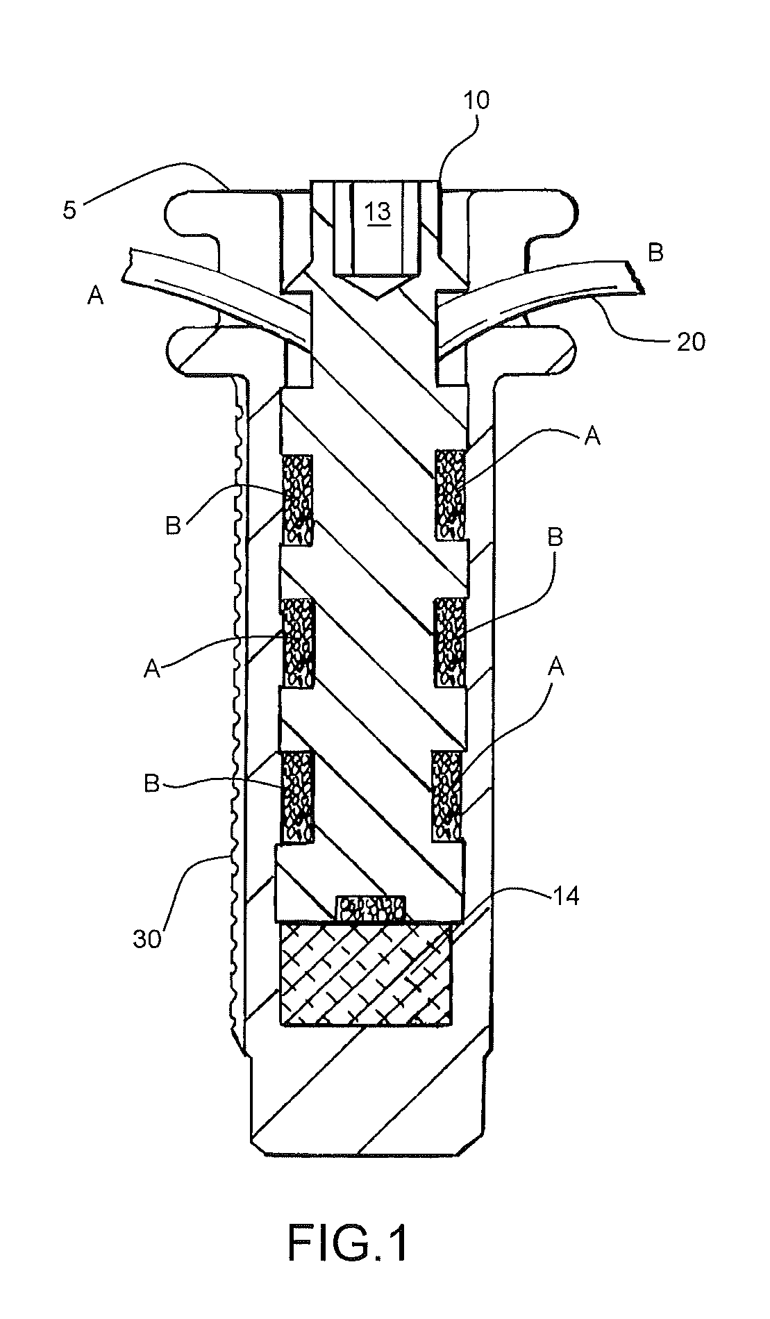
[0028]In accordance with an embodiment of the present invention a novel anchor assembly 1 is securely anchored to bone to attach a synthetic or biologic tether or suture 20. (Tether and suture are used interchangably herein to refer to the material attached to the bone anchor assembly for forming an internal bracing system according to an embodiment of the present invention.) The anchor assembly 1 includes an anchor member 5 and a central set screw 10. The anchor member 5 and set screw 10 are made from biocompatible, high strength materials. Details of the anchor member 5 are illustrated in FIGS. 4-9. Details of the central set screw 10 are illustrated in FIG. 10. The tether 20 is connected to the anchor assembly 1 through interaction of the anchor member 5 and the set screw 10. The attachment of the tether 20 allows dynamic movement of the tether 20 without high risk of failu...


PUM


Abstract

An internal bracing system is disclosed for stabilizing a joint such as the knee, shoulder, ankle or the like. The internal bracing system includes an extra-articular tension band mechanism and an anchor assembly therefore. The internal bracing system adds substantial control to unstable joints which is effective in limiting the pathological joint motions and internal slippage. The anchor anchoring assembly designed to affix a tethering device to various bony structures which form a joint, for the purpose of providing stability. The anchor assembly includes an anchor and a set screw. A double helix thread / chamber structure between the anchor and set screw securely holds the tether without binding.

Description

[0001]This application claims benefit of priority under 35. U.S.C. §119(e) of PCT application PCT / US10 / 31532 filed on Apr. 18, 2010, which claims priority to U.S. provisional patent application 61 / 170,446 filed on Apr. 17, 2009, the contents of which are expressly incorporated herein by reference. U.S. patent application Ser. No. 12 / 763,179 is incorporated by reference. The contents of all references cited herein are expressly incorporated by reference.BACKGROUND OF THE INVENTION[0002]1. Field of the Invention[0003]This invention is generally directed toward an internal bracing system for the knee, shoulder, ankle or the like. The internal bracing system is designed to be located on the medial, lateral, anterior, or posterior aspect of the joint in a manner effective to control excessive laxity or traumatic rotatory and / or translational instability of the joint. The invention is more particularly directed toward an internal bracing system having an extra-articular tension band mecha...

Claims


Application Information

Patent Timeline
Patent Type & Authority Patents(United States)
IPC IPC(8): A61B17/84A61B17/04A61B17/86
CPCA61B17/0401A61B17/8625A61B17/864A61B17/8685A61B2017/0414A61B2017/0417A61B2017/045A61B2017/0462
Inventor HODGE, W. ANDREWTEPIC, SLOBODANBRESINA, STEPHEN
Owner ADVANCED BONE ANCHOR
Why Eureka
Try Eureka