Orientation and localization system

a localization system and orientation technology, applied in direction finders using radio waves, measurement devices, instruments, etc., can solve the problems of difficult correction from anisotropies effect, gain equalization, and serious problem of non-isotropic antennas, so as to improve the natural filtering and less quality

Inactive Publication Date: 2015-03-31
MARZOUKI ABDELWAHED +1
View PDF1 Cites 3 Cited by
  • Summary
  • Abstract
  • Description
  • Claims
  • Application Information

AI Technical Summary

Benefits of technology

[0017]It must be noted that an adapted filtering of reflected waves is performed in a way which improves the natural filtering provided by the polarization itself.

Problems solved by technology

It has to be noted also that in the path loss based localization methods, the problem of non-isotropic antennas poses a serious problem since it causes an erroneous estimation of the distances between the nodes.
This makes it difficult to correct from the anisotropies effect through a simple gain equalization.

Method used


Image

  • Orientation and localization system
  • Orientation and localization system
  • Orientation and localization system

Examples


Embodiment Construction

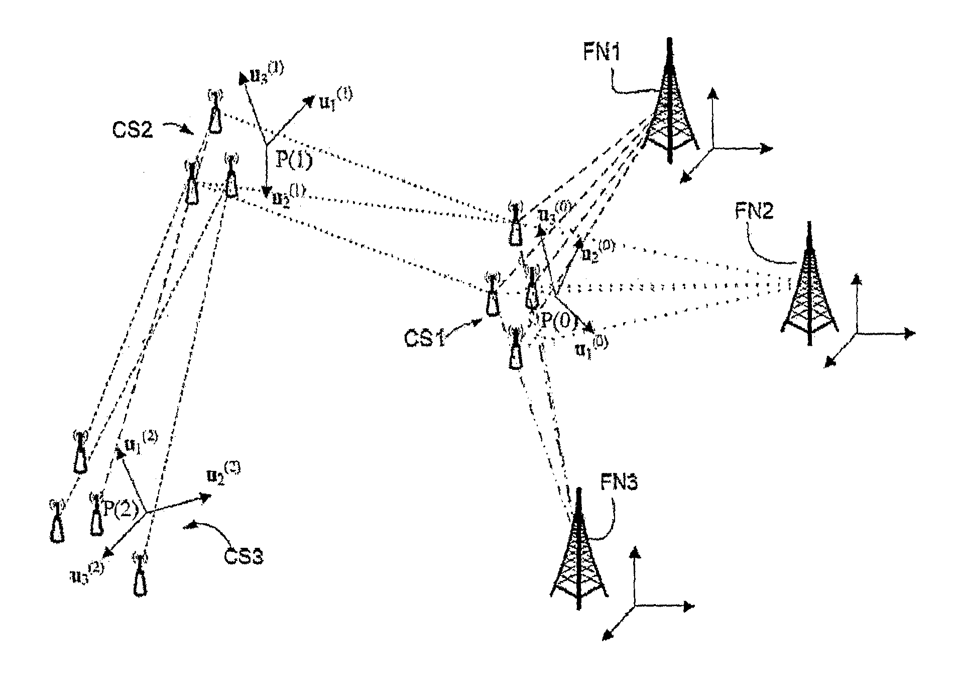
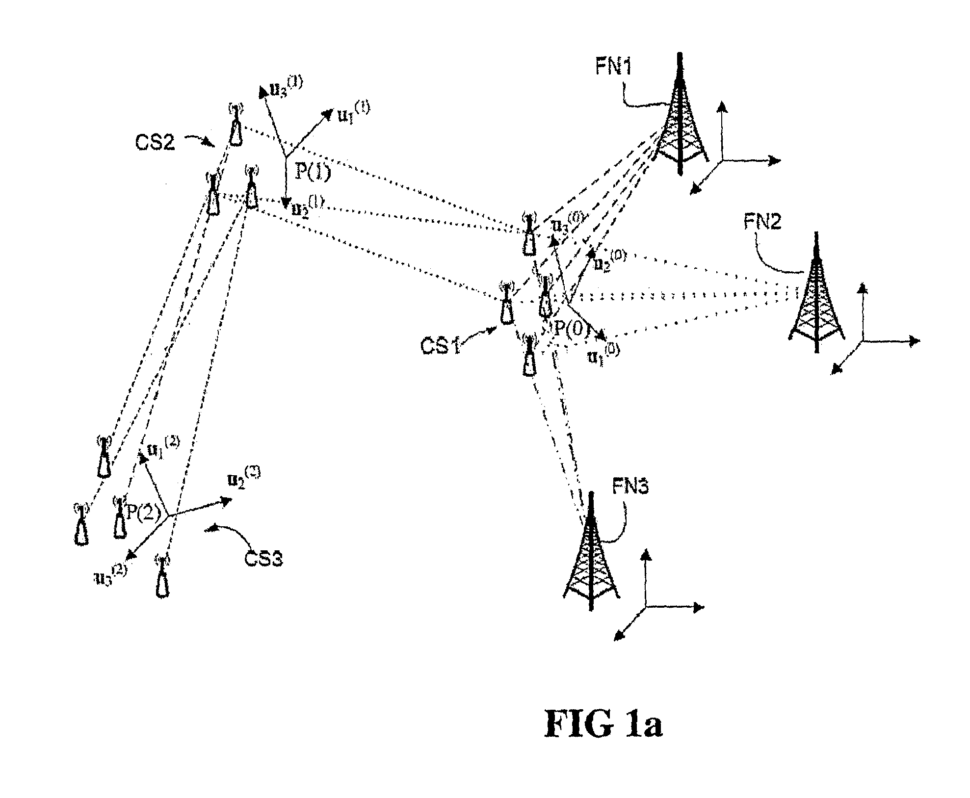
[0031]FIG. 1a is an example of location and orientation sub-system in which the combined spatial diversity and polarization diversity can be used. It comprises a lot of clusters of sensors CS1, CS2, CS3 . . . and a lot of fixed nodes FN1, FN2, FN3. The aim of the invention is to find the orientation and the localization of every node and cluster considered from any cluster or fixed nodes. In this FIG. 1a, reference systems u1(1)u2(1), u3(1), u1(2)u2(2), u3(2), u1(3)u2(3), u3(3) having respectively the origins P(0), P(1), P(2) . . . are allocated to clusters CS1, CS2, CS3 . . . . These reference systems can move relative to the reference system of the fixed nodes FN1, FN2, FN3, . . . .

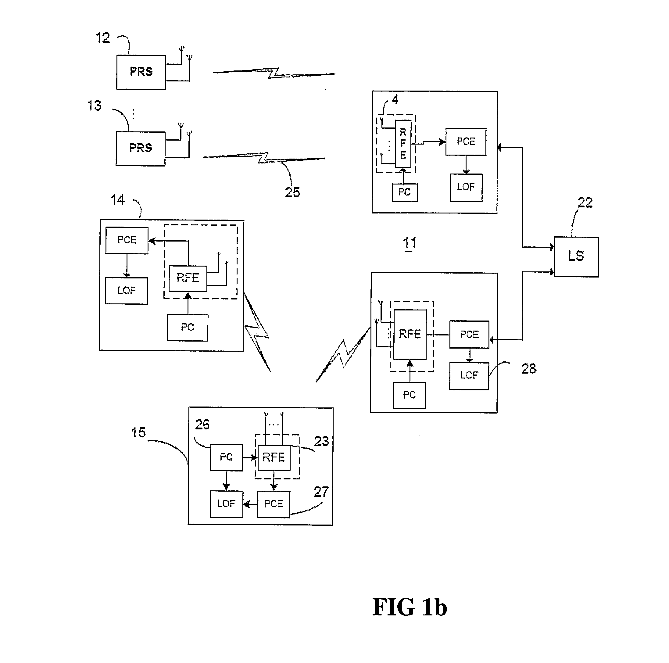
[0032]FIG. 1b shows some details of the radio set incorporated in the mentioned clusters and fixed nodes. It comprises a set of orientation radio stations 11, 12, 13, 14 sharing location and orientation (LO) information through a location server (LS) 25. All said stations 11, 12, 13, 14 can have the sam...


PUM


Abstract

An orientation and localization system is provided with spatial filtering capabilities that combines time polarization and space diversity to detect the direct lines of sight (LOS) and to deliver location and orientation estimates of mobile nodes.

Description

FIELD OF THE INVENTION[0001]The present invention relates generally to positioning in wireless systems, more particularly to an orientation and localization system with spatial filtering capabilities that combines time, polarization and space diversity to detect the line of sight (LOS) and to deliver location and orientation estimates of the mobile nodes.BACKGROUND OF THE INVENTION[0002]Such a system is useful for delivering reliable estimates of the location and the orientation of an object. The system can be used either in a multipath radio environment in which the object, that is the subject of the location and orientation finding, does not share a direct line of sight with the positioning radio station or in a radio environment in which there is at least one line of sight between the object to locate and the positioning station. Such a system is able to operate in indoor and outdoor environments. It provides also spatial filtering solutions that are useful for other wireless net...

Claims


Application Information

Patent Timeline
Patent Type & Authority Patents(United States)
IPC IPC(8): G01S3/16G01S5/04G01S3/02G01S3/72G01S5/02G01S5/14
CPCG01S3/72G01S5/0289G01S5/14
Inventor MARZOUKI, ABDELWAHEDZEGHLACHE, DJAMAL
Owner MARZOUKI ABDELWAHED
Why Eureka
Try Eureka