High efficiency gas-fired water heater

a high-efficiency, gas-fired water heater technology, applied in the direction of combustion types, combustion methods, combustion using lumps and pulverizing fuels, etc., can solve the problems of increasing stringent government efficiency requirements for fuel-fired water heaters of this general typ

Active Publication Date: 2015-04-14
RHEEM MFG CO
View PDF53 Cites 4 Cited by
  • Summary
  • Abstract
  • Description
  • Claims
  • Application Information

AI Technical Summary

Problems solved by technology

While this relatively simple conventional water heater construction has for many years been well suited for its intended water heating purpose, fuel-fired water heaters of this general type are being subjected to increasingly stringent government efficiency requirements.

Method used


Image

  • High efficiency gas-fired water heater
  • High efficiency gas-fired water heater
  • High efficiency gas-fired water heater

Examples


Embodiment Construction

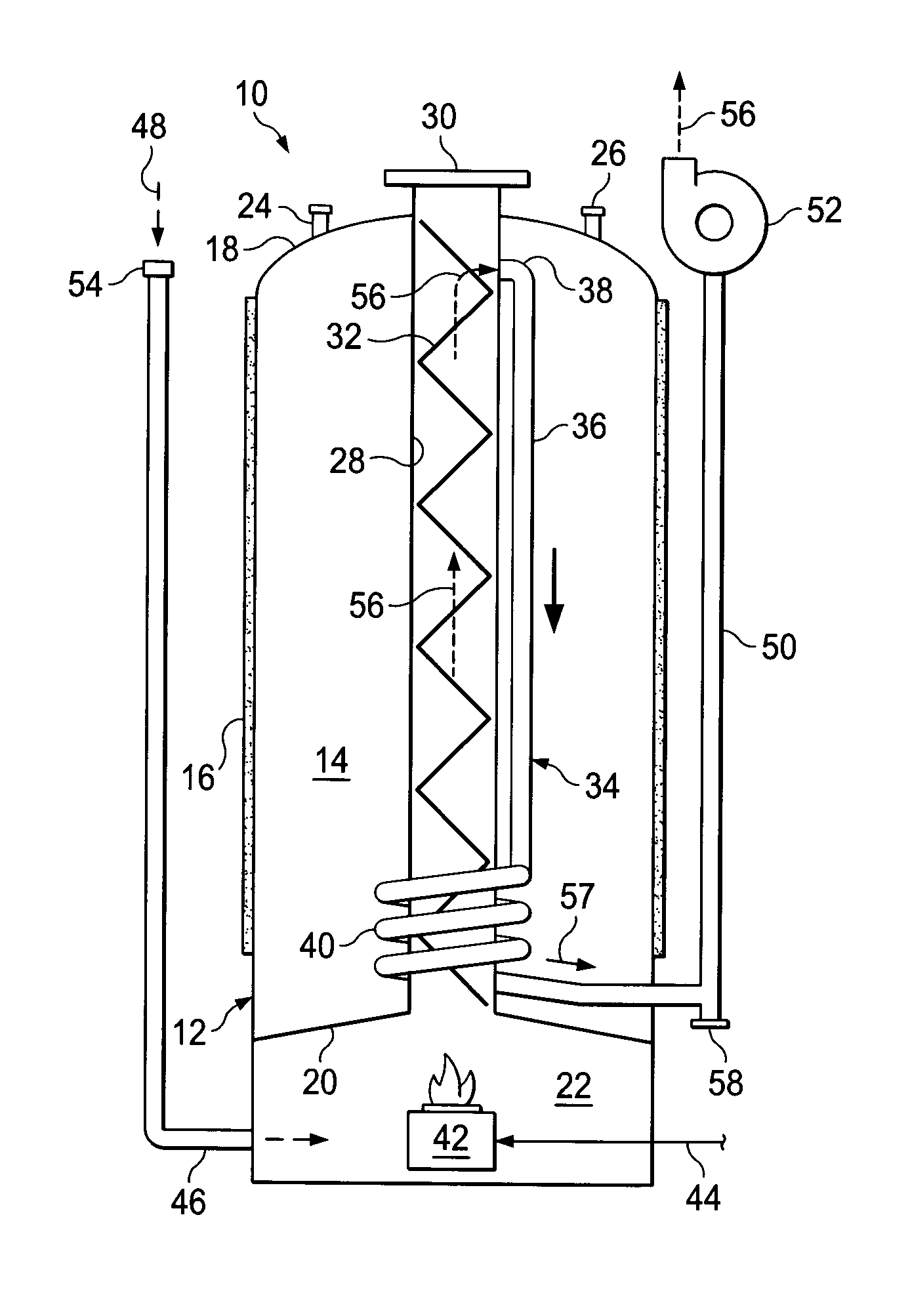
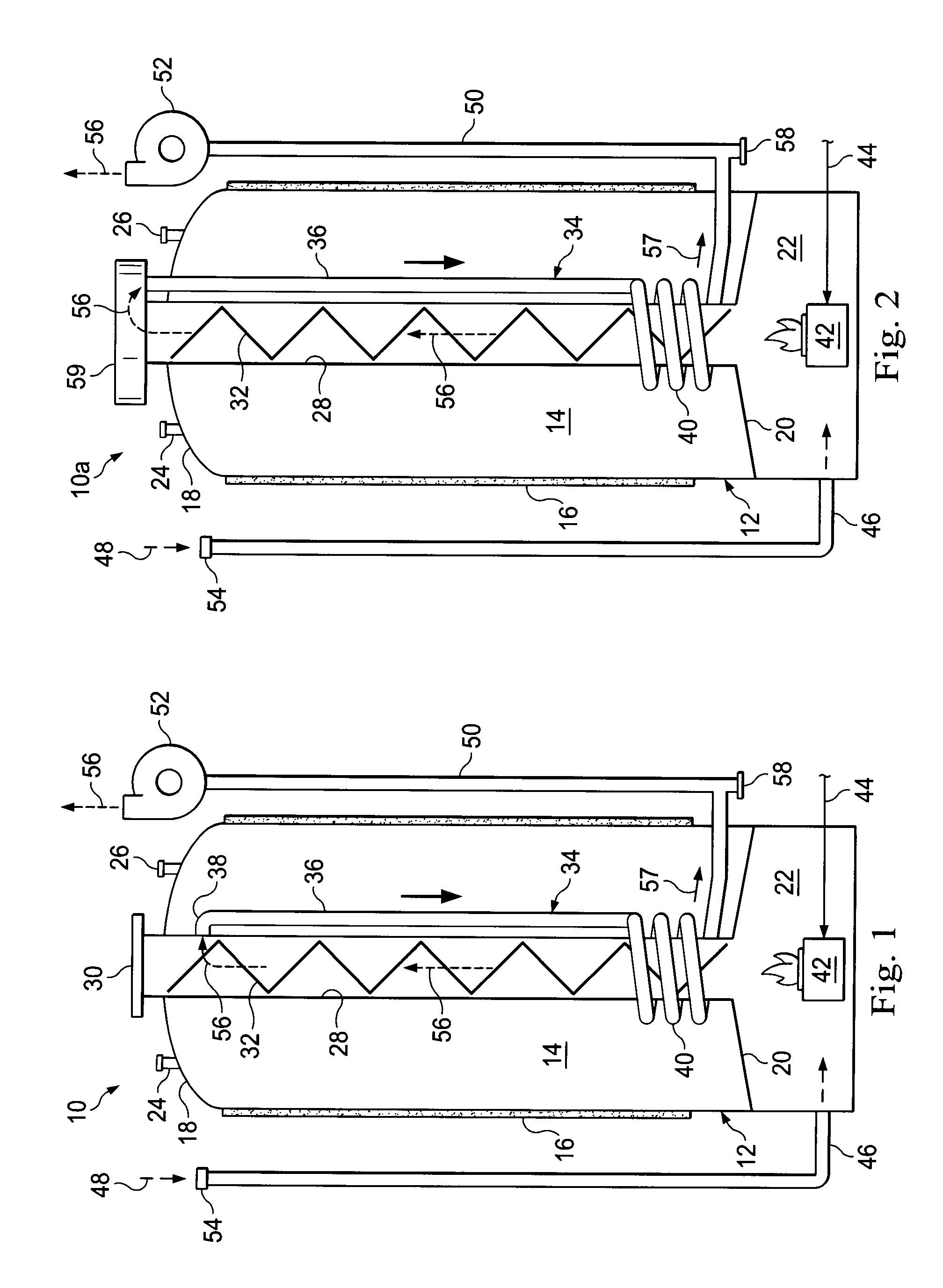
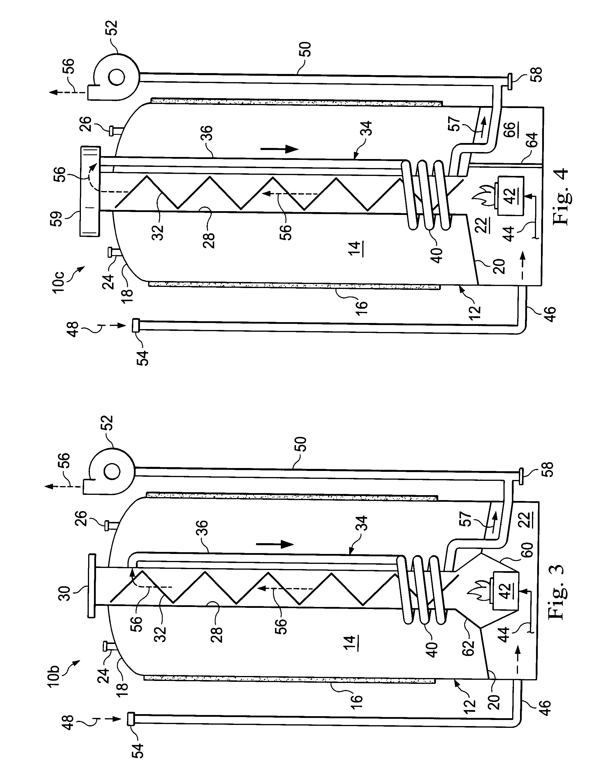
[0012]Turning first to FIG. 1, schematically depicted fuel-fired liquid heating apparatus 10 is representatively a gas-fired water heater, which could be a residential, commercial or industrial type, but could alternatively be apparatus for heating another type of liquid, and / or could be fired using a fuel other than gas. Water heater 10 has a vertically extending tank 12 adapted to hold a quantity of water 14 to be heated, the tank 12 being outwardly surrounded by a suitable insulated jacket structure 16 (only a vertical portion thereof being shown) of conventional construction. Tank 12 has an upper end 18, and a lower end 20 which forms the upper wall of a combustion chamber 22 that underlies the tank 12. Suitable cold water inlet and hot water outlet fittings 24,26 are provided on the upper end 18 of the tank 12.

[0013]Water heater 10 is provided with a flue system including a tubular central metal primary flue 28 which longitudinally extends vertically through a central portion o...


PUM


Abstract

The efficiencies of illustrative embodiments of vertical center flue type fuel-fired base water heaters are improved by installing in the water heaters variously configured tubular condensing type secondary heat exchangers of smaller diameters than the associated center flues. The efficiency increases are achieved with components and manufacturing processes similar to those utilized in the base water heaters and secondary heat exchanger materials similar to those in the tank portions of the base water heaters.

Description

CROSS REFERENCE TO RELATED APPLICATION[0001]The present application claims the benefit of the filing date of provisional U.S. patent application Ser. No. 61 / 311,447 filed Mar. 8, 2010. The entire disclosure of the provisional application is incorporated herein by this reference.BACKGROUND OF THE INVENTION[0002]The present invention generally relates to liquid heating apparatus and, in representatively illustrated embodiments thereof, more particularly provides variously configured fuel-fired high efficiency water heaters.[0003]Fuel-fired water heaters of conventional construction typically have a glass-lined metal tank adapted to store a quantity of pressurized water received from a source such as a city water supply. A combustion chamber having a fuel burner associated therewith is positioned in a heat exchange relationship with the tank, usually at the upper or lower end thereof, and communicates with a central flue extending vertically through the tank water. During firing of the...

Claims


Application Information

Patent Timeline
Patent Type & Authority Patents(United States)
IPC IPC(8): F24H1/18F24H1/20F24H8/00
CPCF24H1/18Y02B30/00
Inventor BOROS, JOZEFZHANG, QIANSEMBA, YOSHIKITHENAPPAN, SUBBU
Owner RHEEM MFG CO
Why Eureka
Try Eureka