Spray paint can spraying accessory

a spraying accessory and spraying technology, applied in spray booths, spraying, packaging, etc., can solve the problems of not being able to adapt to spraying devices specifically, spraying devices not being able to direct spraying inwardly about focal points, and apparatus not being able to adapt to spraying

Inactive Publication Date: 2015-06-23
FODOR ATTILA P
View PDF30 Cites 17 Cited by
  • Summary
  • Abstract
  • Description
  • Claims
  • Application Information

AI Technical Summary

Benefits of technology

[0026]Another object of the invention is to provide a spraying accessory that can be installed and removed from a can of spray paint, and which can be cleaned, and re-used.

Problems solved by technology

However, the spraying device is not a device specifically adapted for use with a spray can, and which can selectively paint around a cylindrical or circular object.
However, the C-shaped fluid sprinkler is not adapted to directed paint inwardly about a focal point, and in conjunction with a can of spray paint in order to paint a cylindrical or circular object.
However, the apparatus does not include an assembly that directs a plurality of spray nozzles inwardly about a focal point in order to paint a cylindrical or circular shaped object, and which attaches to and selectively operates with a spray paint can.
However, the quick disconnect is not a spraying accessory for use with a spray paint can, and which directs spray nozzles inwardly about a focal point in order to paint around a cylinder or circular object.
However, the hoop-shaped dispenser is not in fluid communication with a spray paint can, and does not include an opening to enable ingress and egress of a cylinder or circularly shaped object.
However, the device is adapted to paint an inner surface of a golf cup, and not around an exterior surface.
However, the air brush does not include an assembly that directs spray paint inwardly about a focal point in order to paint an exterior surface of a cylinder or circular object.
However, the pipe paint roller is not in fluid communication with a can of spray paint, and also does not include an assembly of spray nozzles that direct paint inwardly about a focal point.

Method used


Image

  • Spray paint can spraying accessory
  • Spray paint can spraying accessory
  • Spray paint can spraying accessory

Examples


Embodiment Construction

[0036]The following detailed description is merely exemplary in nature and is not intended to limit the described embodiments of the application and uses of the described embodiments. As used herein, the word “exemplary” or “illustrative” means “serving as an example, instance, or illustration.” Any implementation described herein as “exemplary” or “illustrative” is not necessarily to be construed as preferred or advantageous over other implementations. All of the implementations described below are exemplary implementations provided to enable persons skilled in the art to practice the disclosure and are not intended to limit the scope of the appended claims. Furthermore, there is no intention to be bound by any expressed or implied theory presented in the preceding technical field, background, brief summary or the following detailed description.

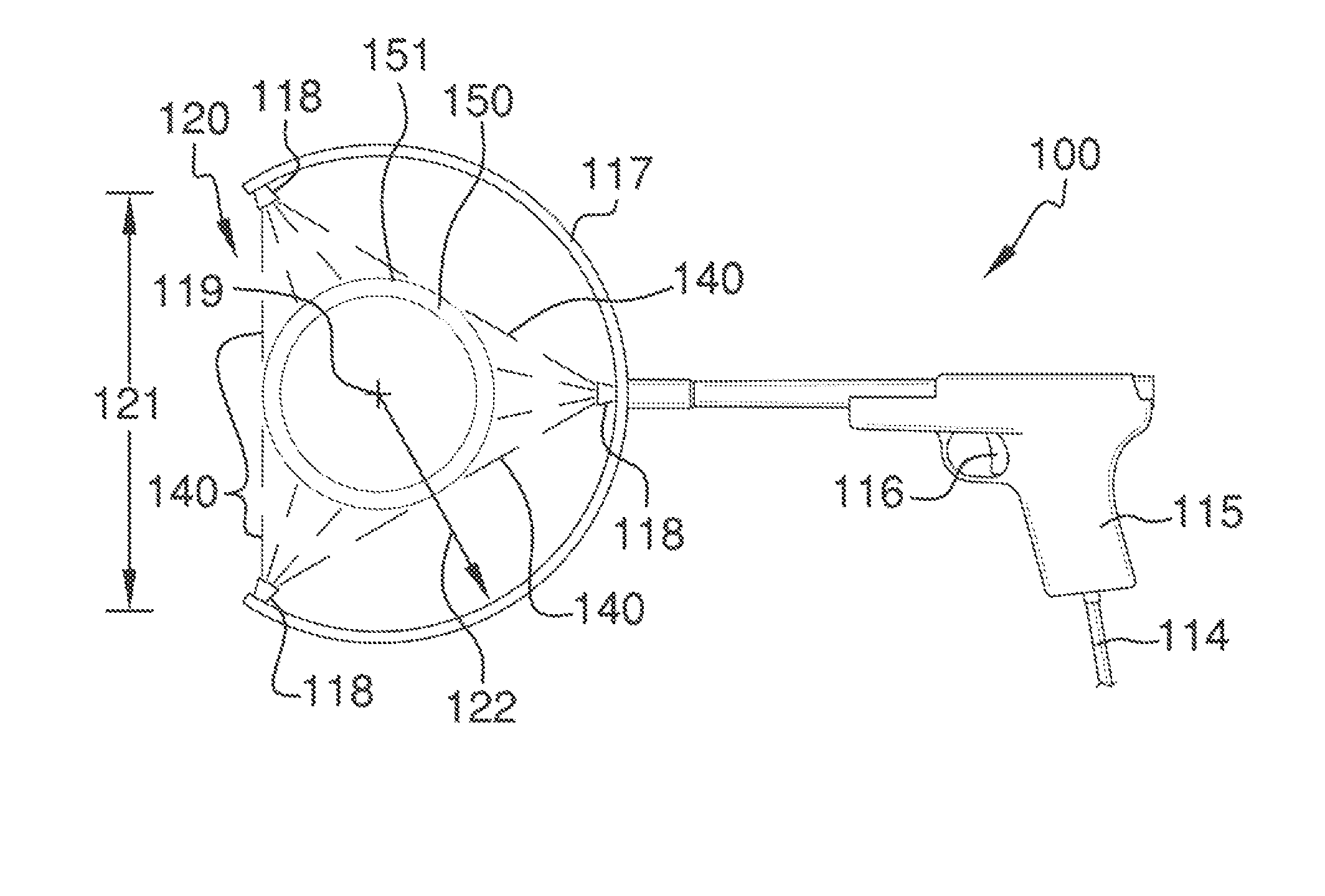
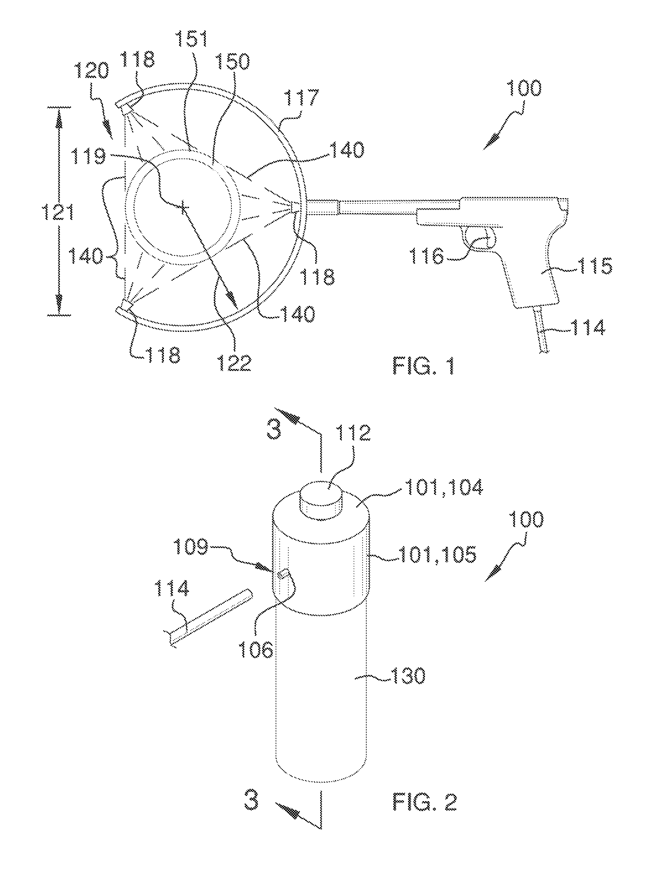
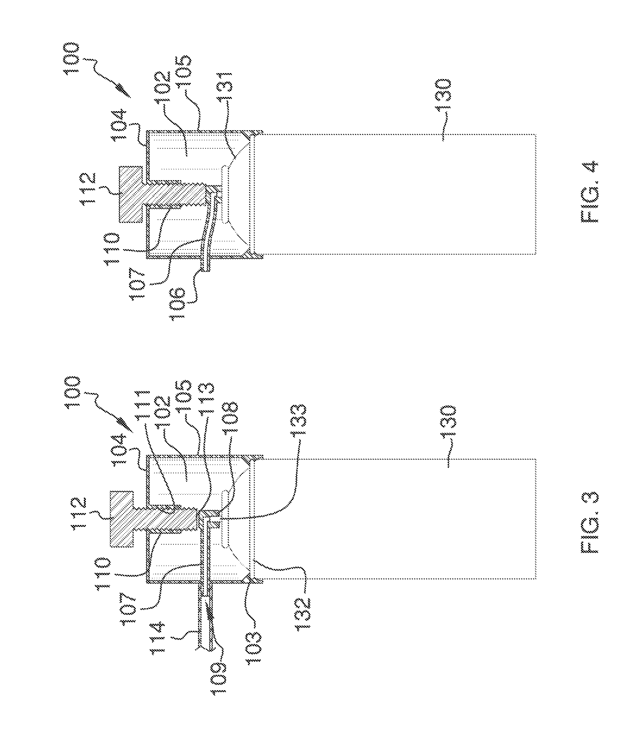
[0037]Detailed reference will now be made to the preferred embodiment of the present invention, examples of which are illustrated in FIGS. ...


PUM


Abstract

The spray paint can spraying accessory attaches onto an existing can of spray paint, and which is able to direct paint inwardly around a focal point in order to paint a cylindrical or circular object. The spray paint can accessory includes a nozzle housing that attaches atop of a spray paint can, and a can nozzle that attaches onto the outlet tube of the existing spray paint can. A spray gun hose connects with the can nozzle to direct paint to a spray gun having a plurality of paint nozzles positioned along an assembly, and which direct paint inwardly around a focal point. The assembly and paint nozzles include an opening to enable ingress and egress of the object to be painted. The can nozzle housing includes a threaded member that upon rotation engages the can nozzle downwardly thereby operating the outlet tube of the spray paint can.

Description

CROSS REFERENCES TO RELATED APPLICATIONS[0001]Not ApplicableSTATEMENT REGARDING FEDERALLY SPONSORED RESEARCH[0002]Not ApplicableREFERENCE TO APPENDIX[0003]Not ApplicableBACKGROUND OF THE INVENTION[0004]A. Field of the Invention[0005]The present invention relates to the field of spray cans, more specifically, an accessory that attaches onto a spray can, and which provides a sprayer accessory for use therewith.[0006]A traditional spray can features a nozzle that when depressed from above, shall direct a spray of the contents of the can. Sometimes, it is necessary to need additional directional capabilities for use with a spray can. This is especially true, where the object to be painted is cylindrically shaped, like a pipe. In said situation, it may be desirable to direct the paint spray at multiple inward directions in order to spray the circumferential surface of said cylindrical object.[0007]The device of the present application seeks to address the need associated with an accessor...

Claims


Application Information

Patent Timeline
Patent Type & Authority Patents(United States)
IPC IPC(8): B05B1/18B05B1/20B05B9/01B05B13/04B05B13/02B65D83/20
CPCB05B13/0436B65D83/203B65D83/205B05B1/207B05B1/20B05B9/01B05B13/0207B65D83/207B65D83/24B05B16/405
Inventor FODOR, ATTILA P.
Owner FODOR ATTILA P
Why Eureka
Try Eureka