Linear drawing machine and method for linear drawing of a workpiece through a drawing ring

a technology of linear drawing and drawing ring, which is applied in the direction of drawing dies, manufacturing tools, metal working apparatuses, etc., can solve the problems of limited implementation requirements, axial oscillation, and the inability to achieve uniform mass distribution using these measures, and achieves targeted influence of drawing results and engagement in drawing procedures

Active Publication Date: 2015-07-14
SMS GRP GMBH
View PDF18 Cites 0 Cited by
  • Summary
  • Abstract
  • Description
  • Claims
  • Application Information

AI Technical Summary

Benefits of technology

[0015]It is correspondingly the object of the present invention to provide a linear drawing machine according to the species and a linear drawing method according to the species, which allow a more targeted engagement in the drawing procedure and thus a more targeted influence of the drawing result.

Problems solved by technology

Due to the latter measure, the workpiece deforms in its cross-section after the drawing, so that only limited requirements may be placed on the implementation of the cross-section in workpieces drawn in this way.
The interaction between friction and displacement work often ultimately results in axial oscillations, i.e., in oscillations along the drawing directions, which are also known in fixed drawing mandrels, however, in that the rod and / or the holding unit act as a spring at the lengths which are required, as described by Benson in his article “praktische and theoretische Gesichtpunkte bei der Gestaltung fliegender Ziehdorne [Practical and Theoretical Aspects in the Design of Flying Drawing Mandrels]” in der Zeitschrift für Metallkunde [The Magazine for Metallurgy], vol.
However, it has been shown that a uniform mass distribution can hardly be achieved using these measures, because complex changes in the mass distribution are caused by the inclination change of the drawing ring and / or the drawing mandrel, which possibly display the desired effects at one point, but necessarily cause a corresponding disadvantageous effect at another point.
This is also true for eccentric displacements of the drawing ring or the drawing mandrel, for example, according to DE 196 10 642 A1, which also result in complex changes in the mass distribution of this type.

Method used


Image

  • Linear drawing machine and method for linear drawing of a workpiece through a drawing ring
  • Linear drawing machine and method for linear drawing of a workpiece through a drawing ring
  • Linear drawing machine and method for linear drawing of a workpiece through a drawing ring

Examples


Embodiment Construction

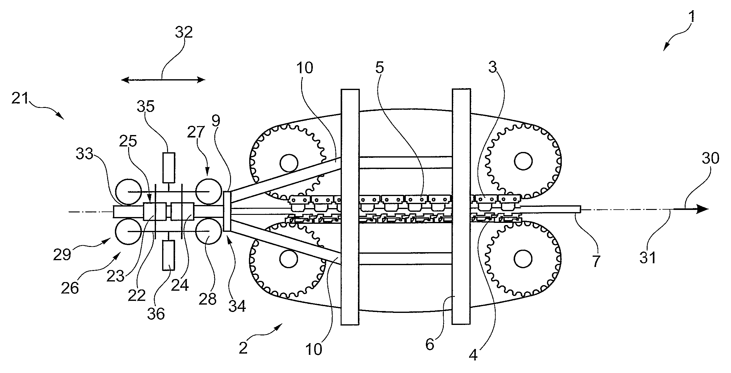
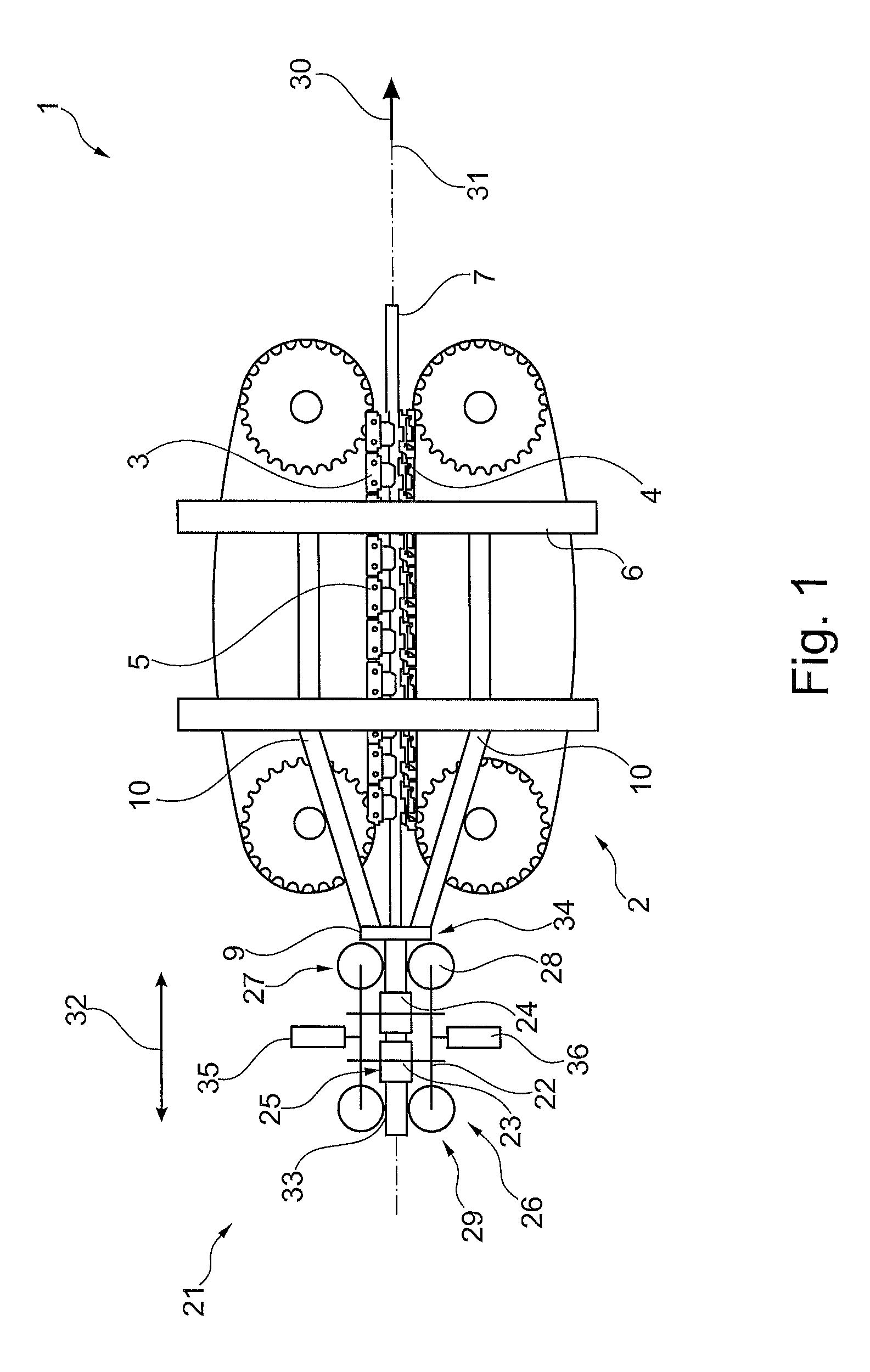
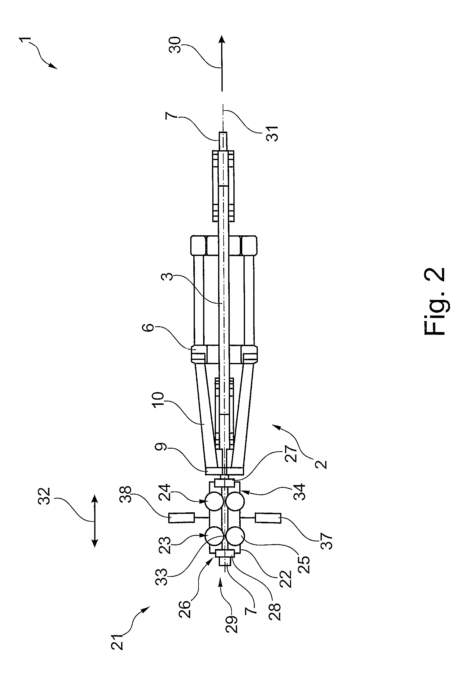
[0050]The linear drawing machine 1 shown in FIGS. 1 through 4 comprises a drawing unit 2, which is implemented in this first exemplary embodiment excerpt shown as a caterpillar-type drawing die. The drawing unit 2 and / or the caterpillar-type drawing die in this regard comprises two revolving drawing chains 3 and 4 (only indicated schematically) in a way known per se, which are equipped with drawing tools 5 (only numbered as examples) and are mounted in a way known per se on a rack 6, an elongate workpiece 7 being able to be drawn through a drawing ring 8 (see FIG. 4), which is mounted on the rack 6, via the drawing tools 5.

[0051]For this purpose, the drawing ring 8 is mounted in a plate-like drawing ring mount 9, which relays the traction forces acting thereon into the remaining rack 6 via mount carriers 10.

[0052]It is obvious that without deviating from the basic idea of the present invention, instead of a caterpillar-type drawing die shown as an example here as the drawing unit 2,...


PUM

PropertyMeasurementUnit
mass distributionaaaaaaaaaa
heightaaaaaaaaaa
diameteraaaaaaaaaa

Abstract

In order to allow a more targeted intervention in a drawing procedure, in particular on a linear drawing device, the invention proposes a linear drawing machine for the linear drawing of a workpiece through a drawing ring, a drawing unit, in which one or more drawing tools grasp the workpiece and draw it linearly in the drawing direction, being situated behind the drawing ring, the linear drawing device being distinguished in particular by a drawing ring which is situated fixed in relation to the drawing direction during the drawing procedure, preferably perpendicularly, and by a workpiece guide situated in front of the drawing ring in the drawing direction, which is displaceable perpendicular to the drawing direction.

Description

CROSS REFERENCE TO RELATED APPLICATIONS[0001]This application is a divisional of and Applicant claims priority under 35 U.S.C. §§120 and 121 of U.S. application Ser. No. 12 / 584,748 filed on Sep. 11, 2009, which claims priority under 35 U.S.C. §119 from German Patent Application No. 10 2008 047 260.3 filed on Sep. 14, 2008, the disclosures of each of which are hereby incorporated by reference. A certified copy of priority German Patent Application No. 10 2008 047 260.3 is contained in parent U.S. application Ser. No. 12 / 584,748. The International Application under PCT article 21(2) was not published in English.BACKGROUND OF THE INVENTION[0002]1. Field of the Invention[0003]The invention relates, on the one hand, to a linear drawing machine for the linear drawing of a workpiece through a drawing ring, a drawing unit, in which one or more drawing tools grasp the workpiece and draw it linearly in the drawing direction, being situated behind the drawing ring. On the other hand, the inven...

Claims


Application Information

Patent Timeline
Patent Type & Authority Patents(United States)
IPC IPC(8): B21C1/22B21C3/16B21C3/14B21C3/04B21C1/34B21C1/24B21C1/30B21C51/00
CPCB21C1/22B21C1/24B21C1/30B21C1/34B21C3/04B21C3/14B21C3/16B21C51/00
Inventor CORDER, ANTHONY JAMES
Owner SMS GRP GMBH
Why Eureka
Try Eureka