Connection assembly

a technology of connecting parts and assembly parts, which is applied in the direction of soil shifting machines/dredgers, constructions, etc., can solve the problems of weakened adaptors, bending of locking pins, and significant wear of excavating equipment buckles during us

Active Publication Date: 2015-09-01
TALON ENG
View PDF15 Cites 9 Cited by
  • Summary
  • Abstract
  • Description
  • Claims
  • Application Information

AI Technical Summary

Benefits of technology

[0007]According to one aspect of the present invention there is provided a coupling for connecting a wear member to a base, the base including a first bearing surface, the wear member including a second bearing surface; the coupling including a rotatable lock having a first face arranged to bear against the first bearing surface and a second face arranged to bear against the second bearing surface, the relative positions of the first and second face varying around a central axis of the lock, such that in use rotation of the lock alters the distance between the first and second bearing surfaces.
[0019]In accordance with a second aspect of the present invention there is provided a coupling for connecting a wear member to a base, the base including a first bearing surface, the wear member including a second bearing surface; the coupling including a rotatable lock having a first face arranged to bear against the first bearing surface and a second face arranged to bear against the second bearing surface, the lock having a central axis about which it can be rotated, the first and second face being both axially and circumferentially spaced relative to central axis of the lock, such that in use the lock can be rotated between a position in which the first and second face bear against the first bearing surface and second bearing surface respectively, and a position in which the first face does not bear against the first bearing surface or the second face does not bear against the second bearing surface. This allows for selective engagement and disengagement of the lock by virtue of turning. Although in a preferred embodiment the present invention allows for tightening of the lock, it will be appreciated that in its simplest form the invention may simply act as a latch to engage the coupling.
[0024]In accordance with a fifth aspect of the present invention there is provided a lock for coupling a wear member to a base, the lock including a hollow for engagement with a tool, wherein a plug is contained within the hollow, the plug being resiliently compressible such that a tool can engage with the hollow by compressing the plug. When the tool is removed, the plug can return to its original configuration. In this way, the ingress of dust and particulate matter into the hollow is substantially impeded.

Problems solved by technology

Buckets of excavating equipment are subject to significant abrasive wear during use.
The connection of teeth to adaptors has presented a consistent challenge, and there are many different systems currently available which seek to perform this task in an efficient manner.
Such an arrangement has an inherent problem in that the provision of a bore weakens the adaptor, as well as encouraging stress concentrations within the adaptor.
In addition, locking pins have a tendency to bend in use, and removal of a bent locking pin may be difficult.
These are problematic in that there is usually no ability to adjust or tighten the connection, hence the teeth are liable to become loose.

Method used


Image

  • Connection assembly
  • Connection assembly
  • Connection assembly

Examples


Embodiment Construction

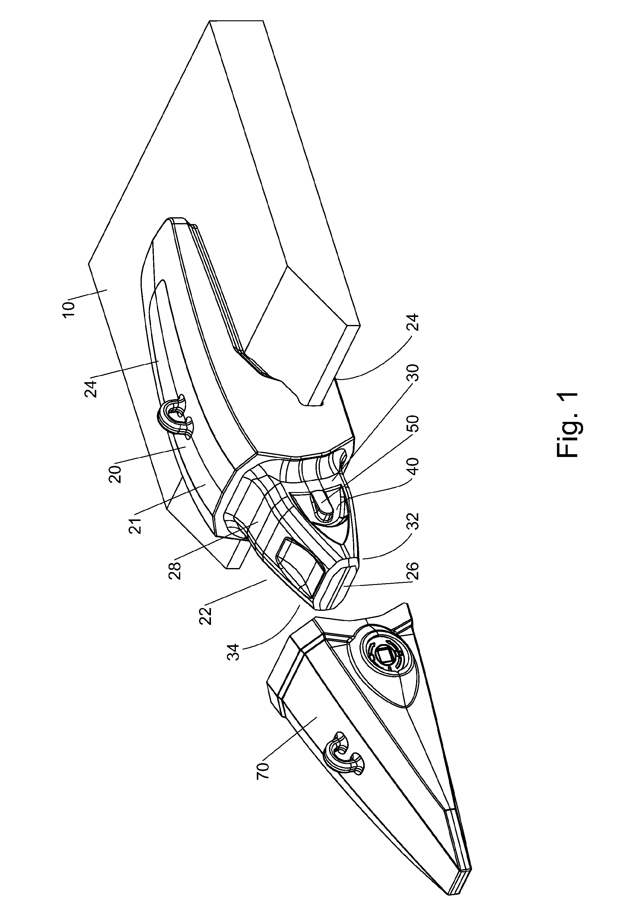
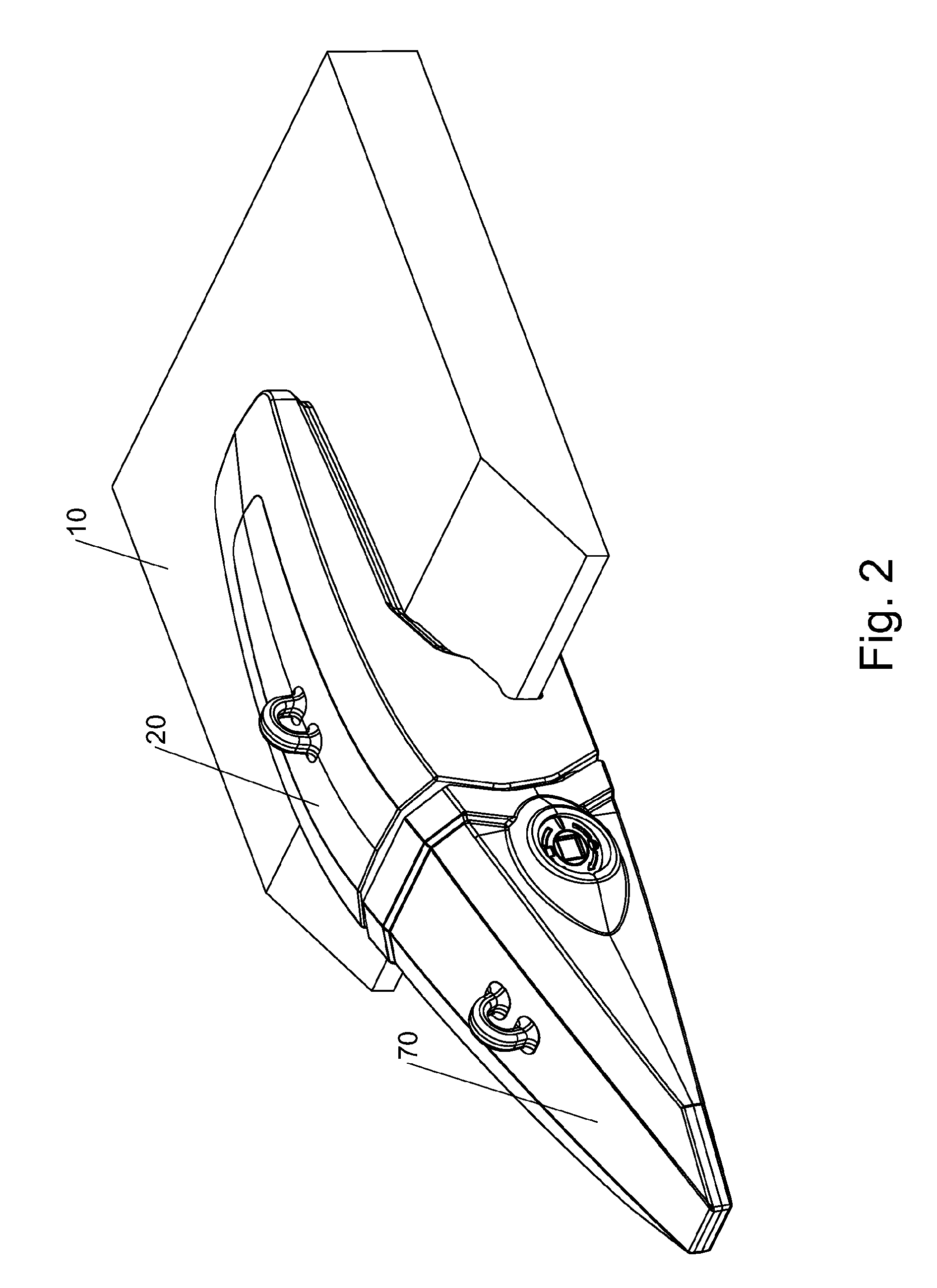
[0076]Referring to the Figures, FIG. 1 shows a portion of a lip 10 of an excavator bucket, onto which is located an adaptor 20. A tooth 70 is shown ready for attachment to the adaptor 20.

[0077]The adaptor 20 has a body part 21; a nose 22 extending forwardly of the body part 21 onto which the tooth 70 can be located, and two legs 24 extending rearwardly of the body part 21 about the lip 10.

[0078]The nose 22 can be more clearly seen in FIGS. 3 and 4. It has a front wall 26, a top 28, a first side wall 30, a bottom 32, and a second side wall 34. The top 28 and the bottom 32 each extend from the body part 21 to the front wall 26. The top 28 and the bottom 32 are not parallel, but are generally angled towards each other such that the nose 22 reduces in height towards the front wall 26, with the front wall 26 being about half the height of the body part 21.

[0079]The first and second side walls 30, 34, each extend from the body portion 21 to the front wall 26. The first and second side wal...


PUM


Abstract

A coupling for connecting ground engaging tools to a lip of an excavator bucket or similar uses an eccentric rotating lock, whereby rotation of the lock alters the distance between bearing surfaces and thus allows tightening of the lock.

Description

CROSS-REFERENCE TO RELATED APPLICATIONS[0001]This is a 371 US national stage application of PCT / AU2011 / 001585, filed Dec. 7, 2011, and entitled “Anchor” which is a Continuation-in-Part of U.S. patent application Ser. No. 13 / 155,472, filed Jun. 8, 2011 and entitled “Anchor” and priority is claimed of AU2010905369, filed Dec. 7, 2010 and AU2011201408, filed Mar. 28, 2011, the disclosures of which are incorporated by reference herein in their entireties as if set forth at length.FIELD OF THE INVENTION[0002]The present invention relates to the connection of wearing elements to machinery. It is particularly directed to the connection of ground engaging tools such as teeth to excavator buckets, but may have wider application.BACKGROUND TO THE INVENTION[0003]Buckets of excavating equipment are subject to significant abrasive wear during use. For this reason, replaceable ground engaging tools (GET) are located about the buckets in the areas most susceptible to wear. A number of different GE...

Claims


Application Information

Patent Timeline
Patent Type & Authority Patents(United States)
IPC IPC(8): E02F9/28
CPCE02F9/2825E02F9/2841E02F9/2891E02F9/28
Inventor HUGHES, BENJAMIN D.
Owner TALON ENG
Why Eureka
Try Eureka