Ophthalmic Instrument Alignment Apparatus and Method of Using Same

Active Publication Date: 2009-06-25
BAUSCH & LOMB INC
View PDF41 Cites 3 Cited by
  • Summary
  • Abstract
  • Description
  • Claims
  • Application Information

AI Technical Summary

Benefits of technology

[0018](D) combining a portion of the light reflected from the eye and a portion of the light reflected from the mirror, and (E) adjusting a length of the test arm such that inte

Problems solved by technology

Such alignment apparatus have limitation on the degree of ac

Method used


Image

  • Ophthalmic Instrument Alignment Apparatus and Method of Using Same
  • Ophthalmic Instrument Alignment Apparatus and Method of Using Same
  • Ophthalmic Instrument Alignment Apparatus and Method of Using Same

Examples


Example

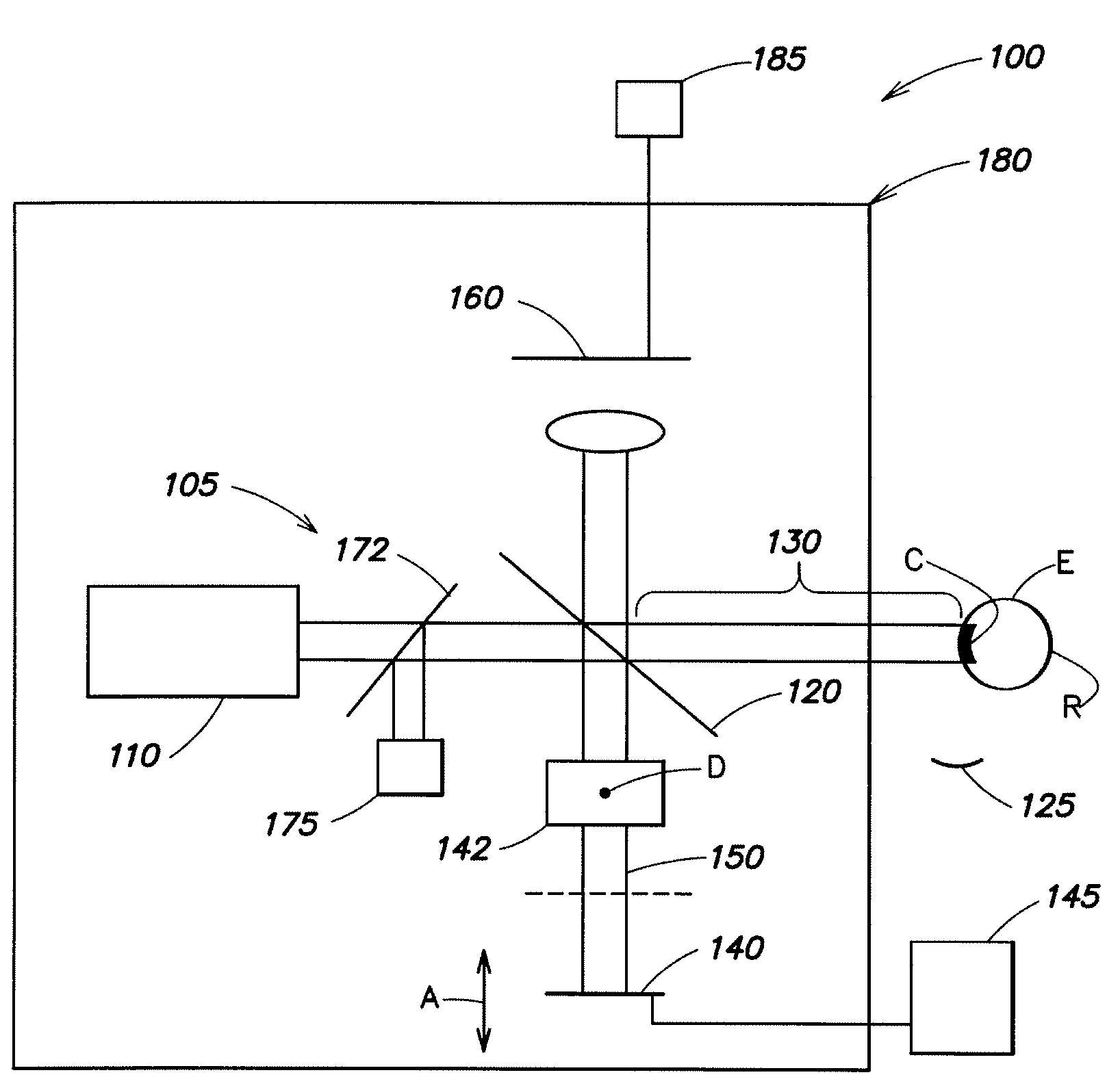
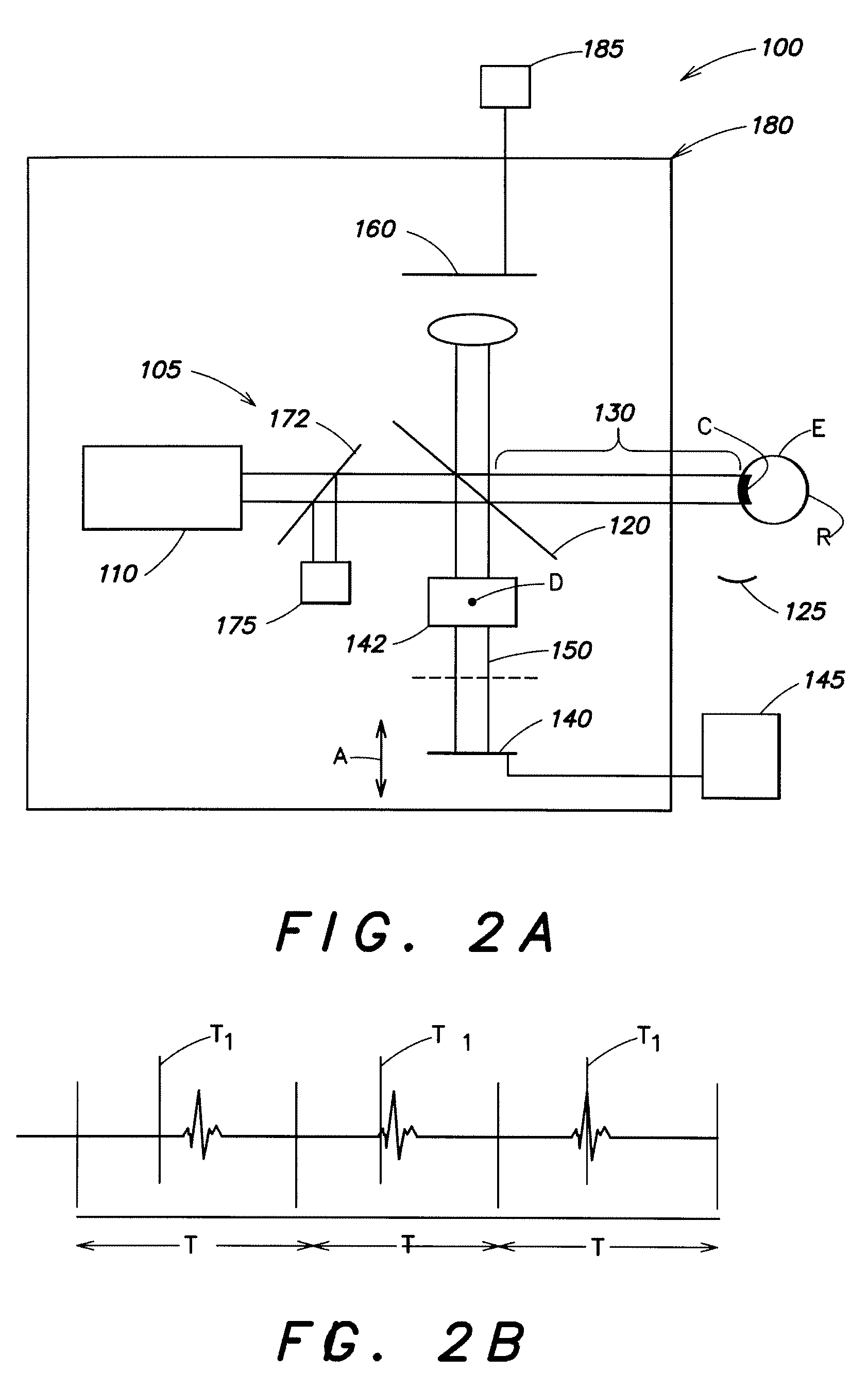
[0027]FIG. 2A is a schematic illustration of an ophthalmic instrument 100 according to aspects of the present invention for use with a subject's eye E. The instrument comprises an interferometer 105 and an ophthalmic apparatus 175. The interferometer and the device are configured and arranged such that an adjustment of a length of a test arm 130 of the interferometer relative to eye E results in a corresponding adjustment of an optical distance from ophthalmic apparatus 175 to eye E. For example, instrument 175 can comprise an ablation laser for performing refractive surgery, at least a portion of an ophthalmic aberrometer, a topographer or a pachymeter.

[0028]In interferometer 105, light from a source 110 is projected onto a beam splitter 120 which projects light onto an eye E in test arm 130 and onto a mirror 140 in a reference arm 150. Light reflected from the eye and light reflected from the mirror are projected onto a detector 160. The light has a coherence length determined by ...


PUM


Abstract

An ophthalmic instrument for use with a subject's eye, comprising an interferometer having a test arm in which the subject's eye is to be positioned and a reference arm, the reference arm including a mirror adapted to be positioned such that the reference arm has a predetermined length, and an ophthalmic apparatus coupled to the interferometer such that, by altering a test arm length, a length between the ophthalmic apparatus and the eye is also altered. The mirror is positioned to achieve the predetermined length and a length of the test arm is adjusted such that interference between the light reflected from the eye and the light reflected from the mirror is achieved, the ophthalmic apparatus is optically aligned with the eye.

Description

CROSS-REFERENCE [0001]This application claims the benefit of Provisional Patent Application No. 61 / 015,781 filed Dec. 21, 2007 which is incorporated by reference herein.FIELD OF INVENTION [0002]The present invention relates to ophthalmic instrument alignment apparatus and methods of use.BACKGROUND OF THE INVENTION [0003]Some ophthalmic procedures use highly precise diagnostic apparatus and / or surgical apparatus. To take advantage of the precision, it is important that the apparatus be accurately aligned with a subject's eye.[0004]Various alignment apparatus are known. FIG. 1 is a schematic illustration of one conventional apparatus for axial alignment with a subject's eye. A first laser 10 and a second laser 20 are aligned so that the beams from the lasers intersect at a location L. The eye is brought to a longitudinal location L (in the z-direction) by observing an image of the light in the beams that is scattered by the subject's cornea C. The image is formed using a camera 50. Wh...

Claims


Application Information

Patent Timeline
IPC IPC(8): A61B3/10
CPCA61B3/152A61F2009/00872A61F9/008
Inventor YOUSSEFI, GERHARDVEITH, RUPERT
Owner BAUSCH & LOMB INC
Why Eureka
Try Eureka