Imaging apparatus for display of maxillary and mandibular arches

Active Publication Date: 2015-09-01
CARESTREAM HEALTH INC +1
View PDF14 Cites 4 Cited by
  • Summary
  • Abstract
  • Description
  • Claims
  • Application Information

AI Technical Summary

Problems solved by technology

Unfortunately, methods for display of maxillary (upper jaw) and mandibular (lower jaw) arch structures require the dental practitioner to analyze the information in one view, then to attend to the patient to address the positioning problem from a different view.

Method used


Image

  • Imaging apparatus for display of maxillary and mandibular arches
  • Imaging apparatus for display of maxillary and mandibular arches
  • Imaging apparatus for display of maxillary and mandibular arches

Examples


Embodiment Construction

[0021]This application claims priority to Provisional U.S. Patent Application Ser. No. 61 / 698,048, filed Sep. 7, 2012 in the names of Julien D. Barneoud, et al., entitled IMAGING APPARATUS FOR DISPLAY OF MAXILLARY AND MANDIBULAR ARCHES, which is incorporated by reference in its entirety.

[0022]The following is a detailed description of the preferred embodiments of the invention, reference being made to the drawings in which the same reference numerals identify the same elements of structure in each of the several figures.

[0023]In the context of the present invention, the term “predominant” has its standard meaning, that is, where there are two variable values or characteristics, the predominant value or characteristic is the more common or more dominant of the two.

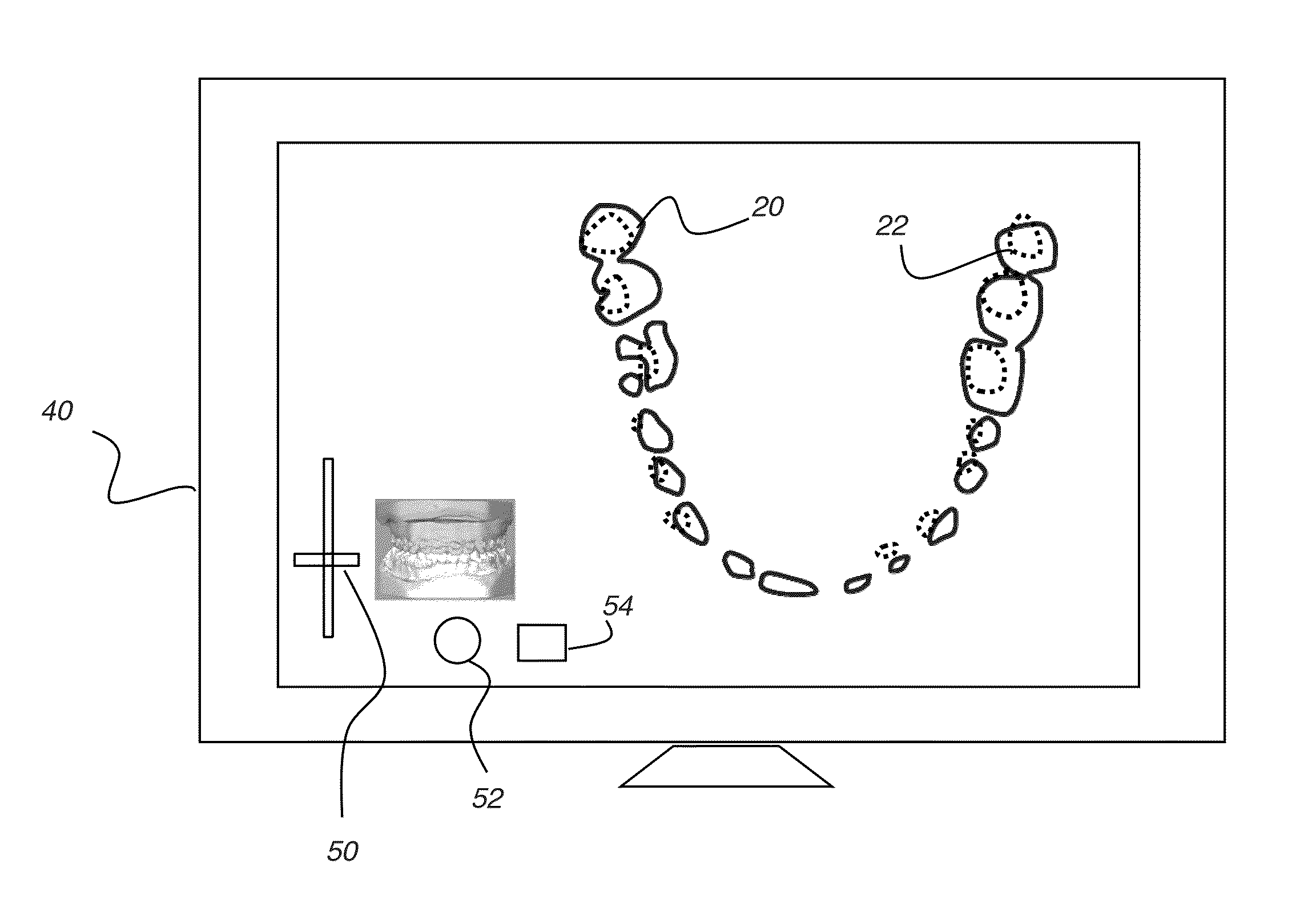
[0024]In the context of the present disclosure, the terms “viewer”, “operator”, and “user” are considered to be equivalent and refer to the viewing practitioner or other person who views and manipulates an image, such as a ...


PUM


Abstract

A method for displaying teeth of a patient, generates a three-dimensional model of the patient's teeth and displays the generated three-dimensional model. A displayed image shows a cross-sectional view of the teeth according to the position of a cutting plane extending through the three-dimensional model. The relative position of the cutting plane is adjustable according to an operator instruction. The orientation of the displayed cross-sectional view is determined by the position of the cutting plane.

Description

CROSS REFERENCE TO RELATED APPLICATIONS[0001]This application claims priority to Provisional U.S. Patent Application Ser. No. 61 / 698,048, filed Sep. 7, 2012 in the names of Julien D. Barneoud, et al., entitled IMAGING APPARATUS FOR DISPLAY OF MAXILLARY AND MANDIBULAR ARCHES, incorporated herein by reference in its entirety.FIELD OF THE INVENTION[0002]The invention relates generally to the field of dental imaging and more particularly to apparatus and methods for visualizing maxillary and mandibular arches and occlusion.BACKGROUND OF THE INVENTION[0003]Orthodontic treatment is widely applied for repositioning teeth and supporting structures to improve tooth function and aesthetics. In conventional orthodontic treatment, appliances such as braces are applied to the patient's teeth by an orthodontist. Over time, the continuing force exerted by the appliance can urge teeth toward more favorable positions, often providing movement to the teeth in incremental steps with successive treatme...

Claims


Application Information

Patent Timeline
Patent Type & Authority Patents(United States)
IPC IPC(8): G06T17/00G06T19/00
CPCG06T17/00G06T19/00G06T2210/41G06T2219/008A61B6/14A61C19/04
Inventor BARNEOUD, JULIEN D.CAPRON-RICHARD, SABRINABOTHOREL, SYLVIEETESSE, RONAN
Owner CARESTREAM HEALTH INC
Why Eureka
Try Eureka