Method and structure for inducing acoustic signals and attenuating acoustic signals

a technology of inducing acoustic signals and attenuating acoustic signals, which is applied in the direction of transducer details, instruments, earpiece/earphone attachments, etc., and can solve problems such as hearing damage and disorientation

Inactive Publication Date: 2015-09-01
STATON TECHIYA LLC
View PDF10 Cites 34 Cited by
  • Summary
  • Abstract
  • Description
  • Claims
  • Application Information

AI Technical Summary

Problems solved by technology

Sudden acoustical shocks, such as a gun blast, explosion, or other high decibel sounds can cause hearing damage and disorientation.

Method used


Image

  • Method and structure for inducing acoustic signals and attenuating acoustic signals
  • Method and structure for inducing acoustic signals and attenuating acoustic signals
  • Method and structure for inducing acoustic signals and attenuating acoustic signals

Examples


Embodiment Construction

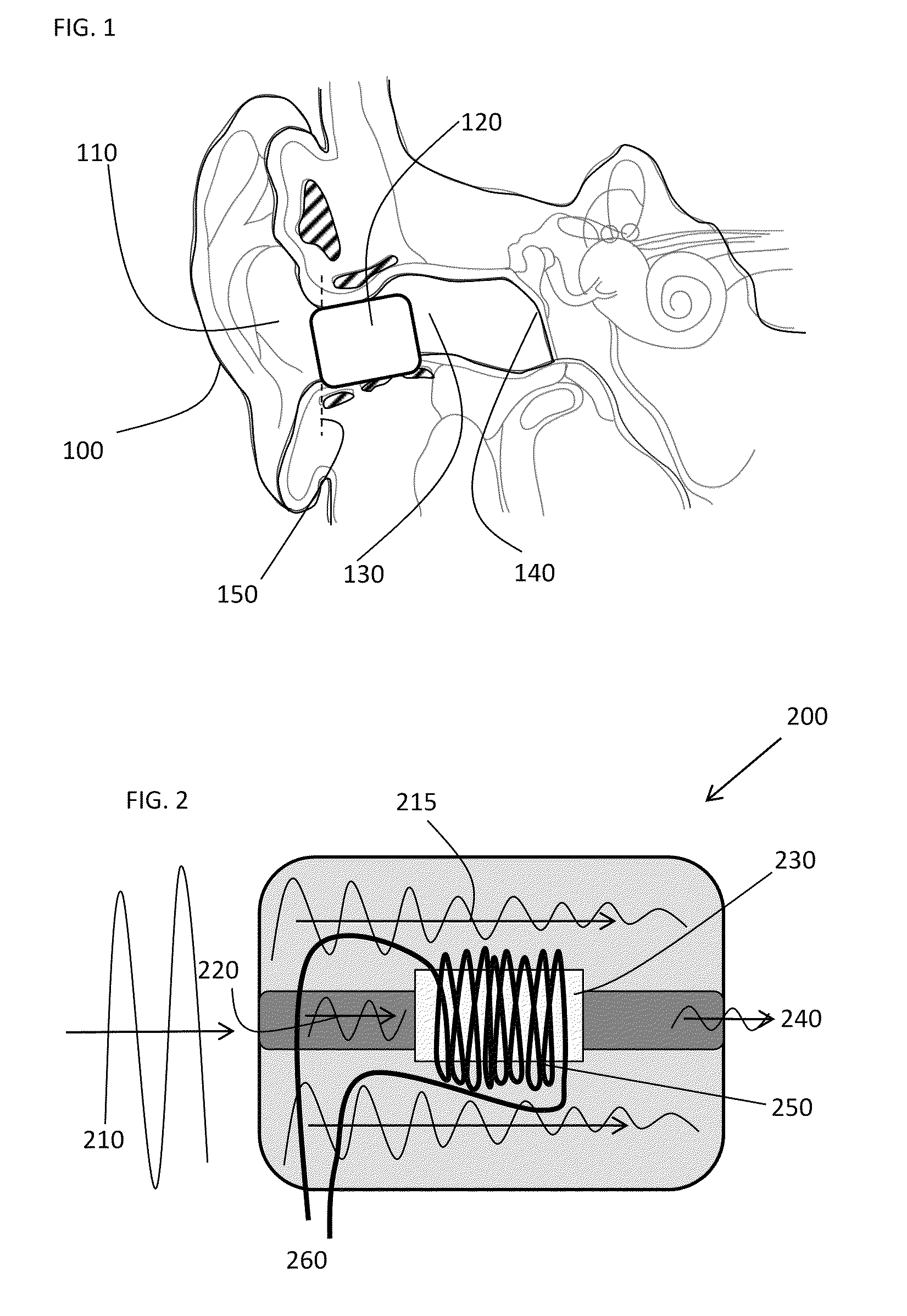
[0013]The following description of exemplary embodiment(s) is merely illustrative in nature and is in no way intended to limit the invention, its application, or uses.

[0014]Exemplary embodiments are directed to or can be operatively used on various wired or wireless earpieces devices (e.g., earbuds, headphones, ear terminal, behind the ear devices or other acoustic devices as known by one of ordinary skill, and equivalents). For example, the earpieces can be without transducers (for a noise attenuation application) or one or more transducers (e.g. ambient sound microphone (ASM), ear canal microphone (ECM), ear canal receiver (ECR)) for monitoring / providing sound. In all of the examples illustrated and discussed herein, any specific values should be interpreted to be illustrative only and non-limiting. Thus, other examples of the exemplary embodiments could have different values.

[0015]Processes, techniques, apparatus, and materials as known by one of ordinary skill in the art may not...


PUM


Abstract

At least embodiment is directed to an earpiece comprising a housing; and a field responsive fluid, where the field responsive fluid is in the housing, where the housing is part of the earpiece, and where the earpiece is configured to vary a field to vary an acoustical property of the field responsive fluid.

Description

CROSS-REFERENCE TO RELATED APPLICATIONS[0001]This application claims the benefit of U.S. provisional patent application No. 61 / 351,290 filed 4 Jun. 2010. The disclosure of which is incorporated herein by reference in its entirety.FIELD OF THE INVENTION[0002]The present invention relates to devices that can be used to control acoustical energy transmitted and more particularly, though not exclusively, a device that can control attenuation or generate acoustical signals.BACKGROUND OF THE INVENTION[0003]Sudden acoustical shocks, such as a gun blast, explosion, or other high decibel sounds can cause hearing damage and disorientation. Accordingly, a system that can monitor the environment and electrically vary the level of attenuation of the sound heard by a user prior to the shock arriving would be useful.BRIEF DESCRIPTION OF THE DRAWINGS[0004]Exemplary embodiments of present invention will become more fully understood from the detailed description and the accompanying drawings, wherein...

Claims


Application Information

Patent Timeline
Patent Type & Authority Patents(United States)
IPC IPC(8): H04R25/00G10K11/162A61F11/08H04R1/10
CPCG10K11/162A61F11/08H04R1/1083H04R1/1091H04R1/42H04R9/027
Inventor KEADY, JOHN P.
Owner STATON TECHIYA LLC
Why Eureka
Try Eureka