Supercharge Your Innovation With Domain-Expert AI Agents!

Lifting column, preferably for height adjustable tables

a technology of lifting column and height adjustable table, which is applied in the direction of rod connection, variable height table, fastening means, etc., can solve the problems of vibration of the table, energy consumption, and vibration of the tabl

Active Publication Date: 2015-09-29
LINAK AS
View PDF19 Cites 4 Cited by
  • Summary
  • Abstract
  • Description
  • Claims
  • Application Information

AI Technical Summary

Benefits of technology

The invention is related to a lifting column system that can adjust the height of a work table. The telescopic members, which make up the columns, are often made of pipe profiles with a random cross section, but a square cross section is the most commonly used. A rectangular cross section is even more effective for differentiating between small and large prestressing. The broadside of the profiles in the guides should be about one and a half times larger than the narrow side. The first, or large, prestressing is provided in a direction across the table top, while the second, or small, prestressing is provided along the table top. The invention can also be used in a height-adjustable work table with a longitudinally extending table top.

Problems solved by technology

A particular problem is vibrations of the table when it is exposed to a horizontal force.
The back and forth movements of the printer head can cause vibrations of the table.
Popularly speaking, the more friction the larger motor and thus energy consumption is required.
There is, however, a limit to how large the overlapping can be.
Another possibility is to use adjustment screws for the prestressing, this is however not particularly manufacturing-friendly.

Method used


Image

  • Lifting column, preferably for height adjustable tables
  • Lifting column, preferably for height adjustable tables
  • Lifting column, preferably for height adjustable tables

Examples


Embodiment Construction

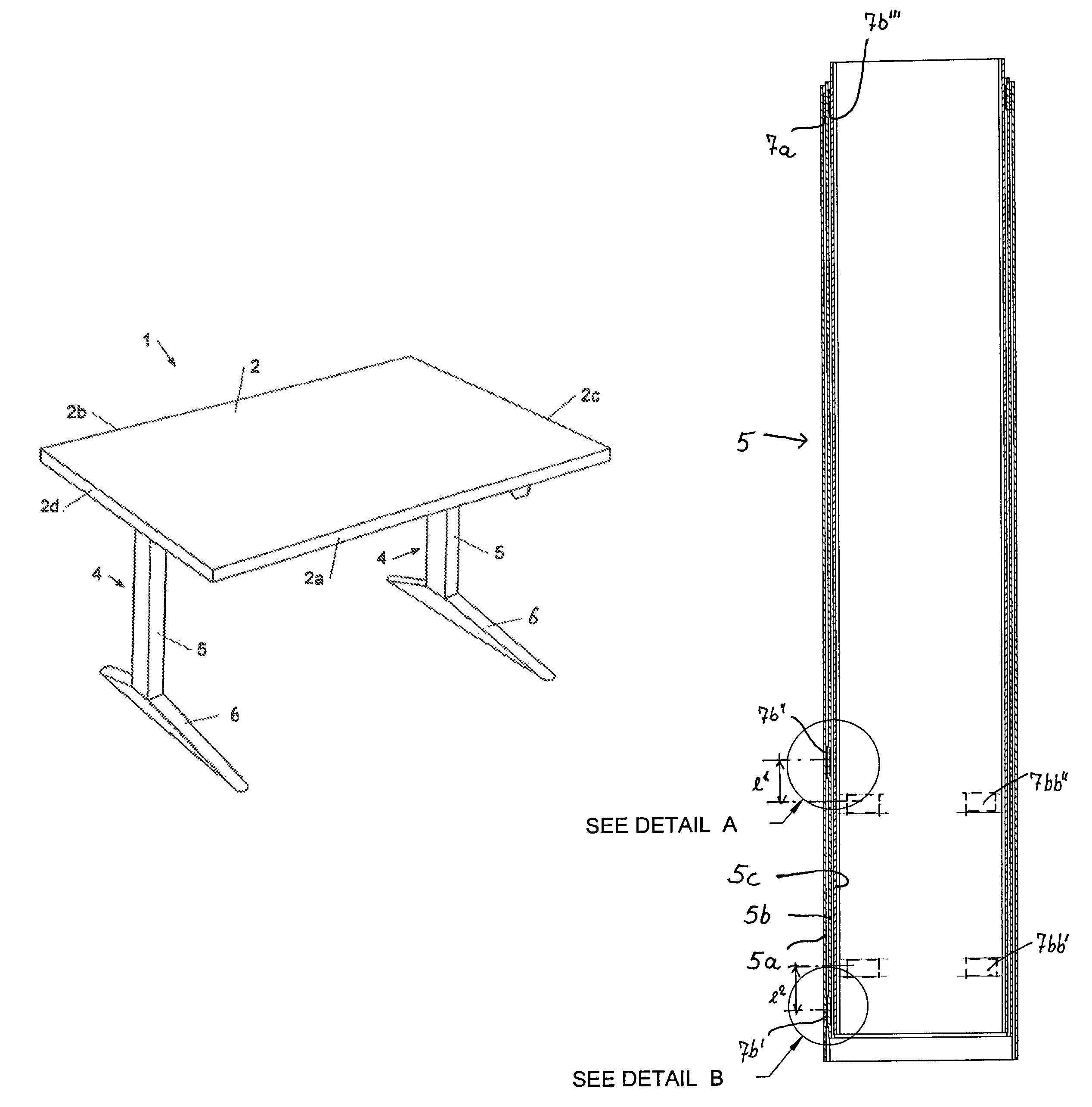
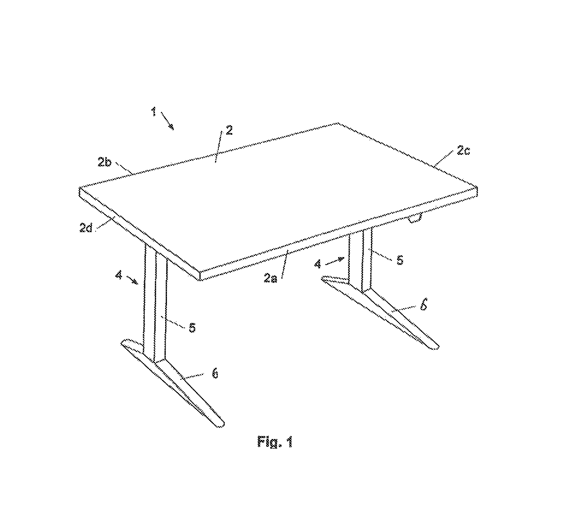
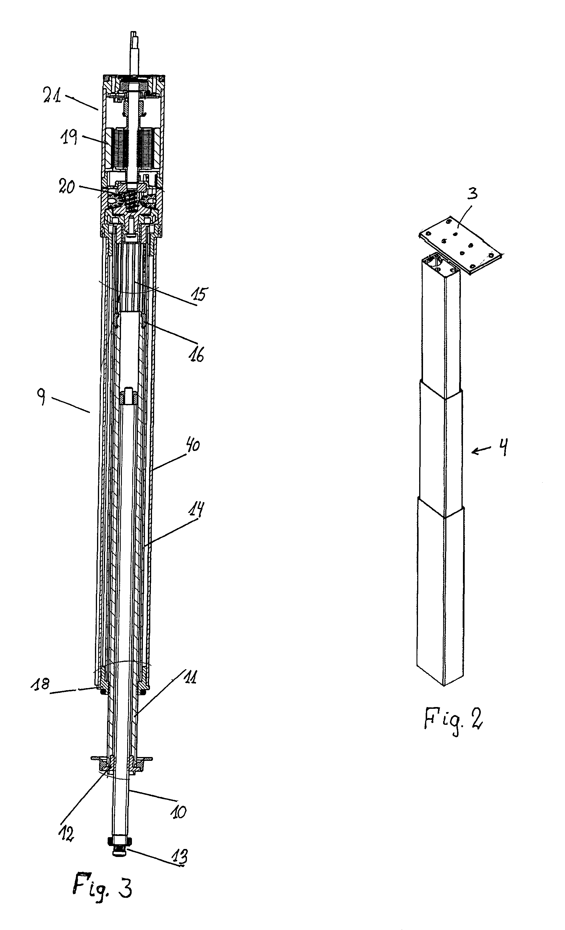
[0030]The height adjustable work table 1 shown in FIG. 1. comprises a table top 2 having a front side 2a (the side where a user of the table is located), a rear side 2b, a right end 2c and a left end 2d. At the right end 2c and the left end 2d, respectively, there is a lifting column 4, which with an upper end is mounted to the table top by means of a mounting plate 3 (see FIG. 2), which is screwed onto the upper end of the lifting column and which further is screwed onto the underside of the table top 2. The bottom part of each of the lifting columns 4 is furnished with an elongated foot 6 extending across the table. In FIG. 2 a lifting column 4 is shown in its fully extended position. It comprises a guide 5 with an outermost member 5a (see FIG. 4), onto which the foot 6 is mounted, an intermediate member 5b and an innermost member 5c. The three members 5a, 5b, 5c of the guide are mutually telescopically arranged, such that the outermost member 5a having the largest cross section i...


PUM


Abstract

A lifting column preferably, for height adjustable tables, includes a guide (5) and a drive unit (9), the guide (5) including at least a first member (5a) and a second member (5b), the members (5a, 5b, 5c) being arranged mutually telescopically relative to each other. At the end of the first member (5a) from which the second member (5b) can be displaced sliders are arranged on an internal side thereof. At the end of the second member (5b) extending into the first member (5a) sliders are likewise arranged on the outside thereof. In a first plane the sliders have a first, a large, prestressing between the first member (5a) and the second member (5b), while the sliders in the second plane have a second, a small, prestressing between the first (5a) and second member (5b). Thus, a good dampening of vibrations of the table is achieved in case of exposure to horizontal forces.

Description

BACKGROUND OF THE INVENTION[0001]1. Field of the Invention[0002]The Invention relates to a lifting column, preferably for height adjustable tables, comprising a guide and a drive unit, where the guide comprises at least a first member and a second member, where the members are mutually telescopically arranged relative to each other, and where a first set of sliders is arranged on an internal side of the first member at the end of the first member into which the second member extends and may be displaced out of, and where a second and third set of sliders are arranged on the outside of the second member at the end of the second member which extends into the first member. The invention further relates to a height adjustable table equipped with at least one such lifting column.[0003]2. The Prior Art[0004]For explanation of the invention reference is made to height adjustable or so-called sit / stand work tables, where the underframe comprises an electrically driven lifting column at each...

Claims


Application Information

Patent Timeline
Patent Type & Authority Patents(United States)
IPC IPC(8): A47B9/20F16B7/14
CPCA47B9/20F16B7/14A47B2200/0054
Inventor RIIS, MARTINRASMUSSEN, ULRIK N.
Owner LINAK AS
Features
  • R&D
  • Intellectual Property
  • Life Sciences
  • Materials
  • Tech Scout
  • Unparalleled Data Quality
  • Higher Quality Content
  • 60% Fewer Hallucinations
Learn More