Wake shaping system for a boat

a technology for shaping systems and boats, applied in the field of wake shaping systems for boats, can solve the problems of large wakes, hulls that do not perform well on public waterways, passengers cannot sit in the back of the boat,

Inactive Publication Date: 2015-10-06
MB SPORTS
View PDF7 Cites 24 Cited by
  • Summary
  • Abstract
  • Description
  • Claims
  • Application Information

AI Technical Summary

Problems solved by technology

The first waterski boats, however, were wooden boats that produced large wakes because of the weight of the boats.
The shape of the hull is optimized to create small, soft wakes for tournament waterskiing, but the hull does not perform well on public waterways, which are often larger and more crowded than private waterski lakes.
In addition, because the ski rope is attached to a ski pylon in front of the engine, passengers cannot sit in the back of the boat while a skier is skiing because the ski rope swings back and forth at head-height above the rear seat.
This configuration “sinks” or “lists” one side of the boat, tipping the boat and creating a large, unsymmetrical wake for wakesurfing on the listed side of the boat at wakesurfing speeds.
Conventional wakesurfing ballast configurations, however, have many disadvantages.
First, by weighting only one side of the boat, the boat is unbalanced and difficult to control at slower speeds.
After a surfer falls, it is difficult and dangerous to return to the fallen surfer at slower speeds and with reduced visibility.
Second, traditional ballast takes up a large portion of the boat's storage capacity.
Third, moving the ballast from one side to the other to create a surf wake on the opposite side can be difficult, time consuming, and cumbersome.
These external pumps often leak and require priming in order to siphon water out of the tanks when emptying.
With internal hard ballast tanks, the ballast tanks may be filled or emptied with internal ballast pumps at the same time, reducing the time to switch sides, but still may take 10 minutes or more, depending on the speed of the pumps.
However, this is inconvenient and requires undesired advanced planning to set the ballast for each rider's desired ballast configuration.

Method used


Image

  • Wake shaping system for a boat
  • Wake shaping system for a boat
  • Wake shaping system for a boat

Examples


Embodiment Construction

[0036]While the making and using of various embodiments of the present disclosure are discussed in detail below, it should be appreciated that the present disclosure provides many applicable inventive concepts that can be embodied in a wide variety of specific contexts. The specific embodiments discussed herein are merely illustrative of specific ways to make and use the disclosure and do not limit the scope of the disclosure.

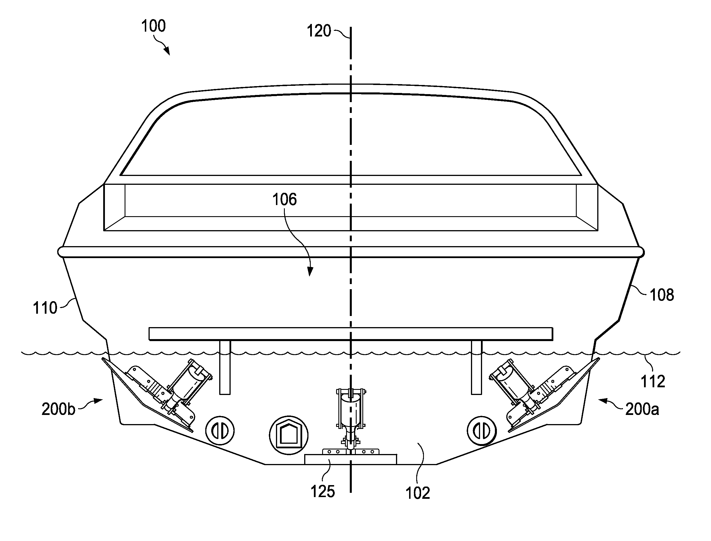
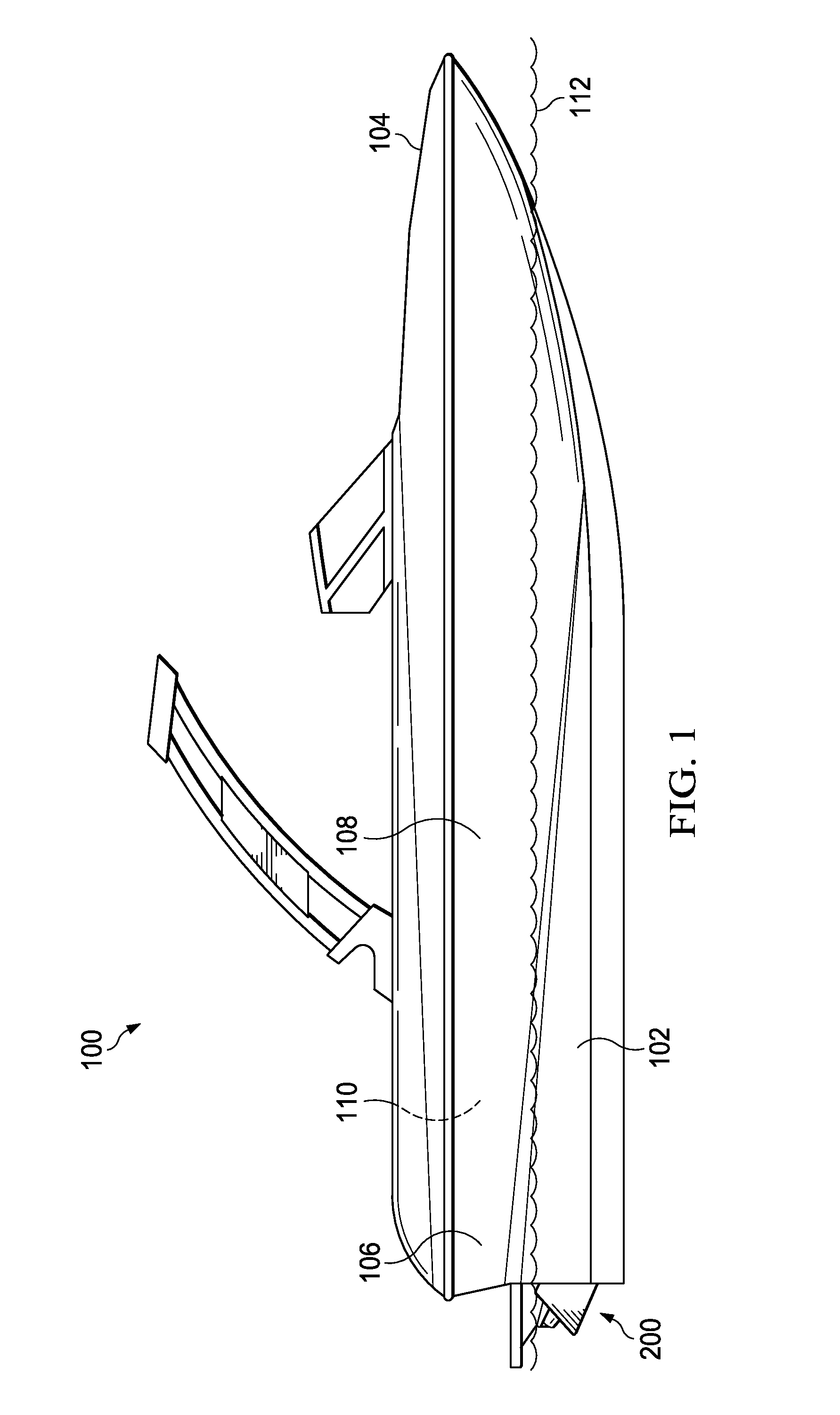
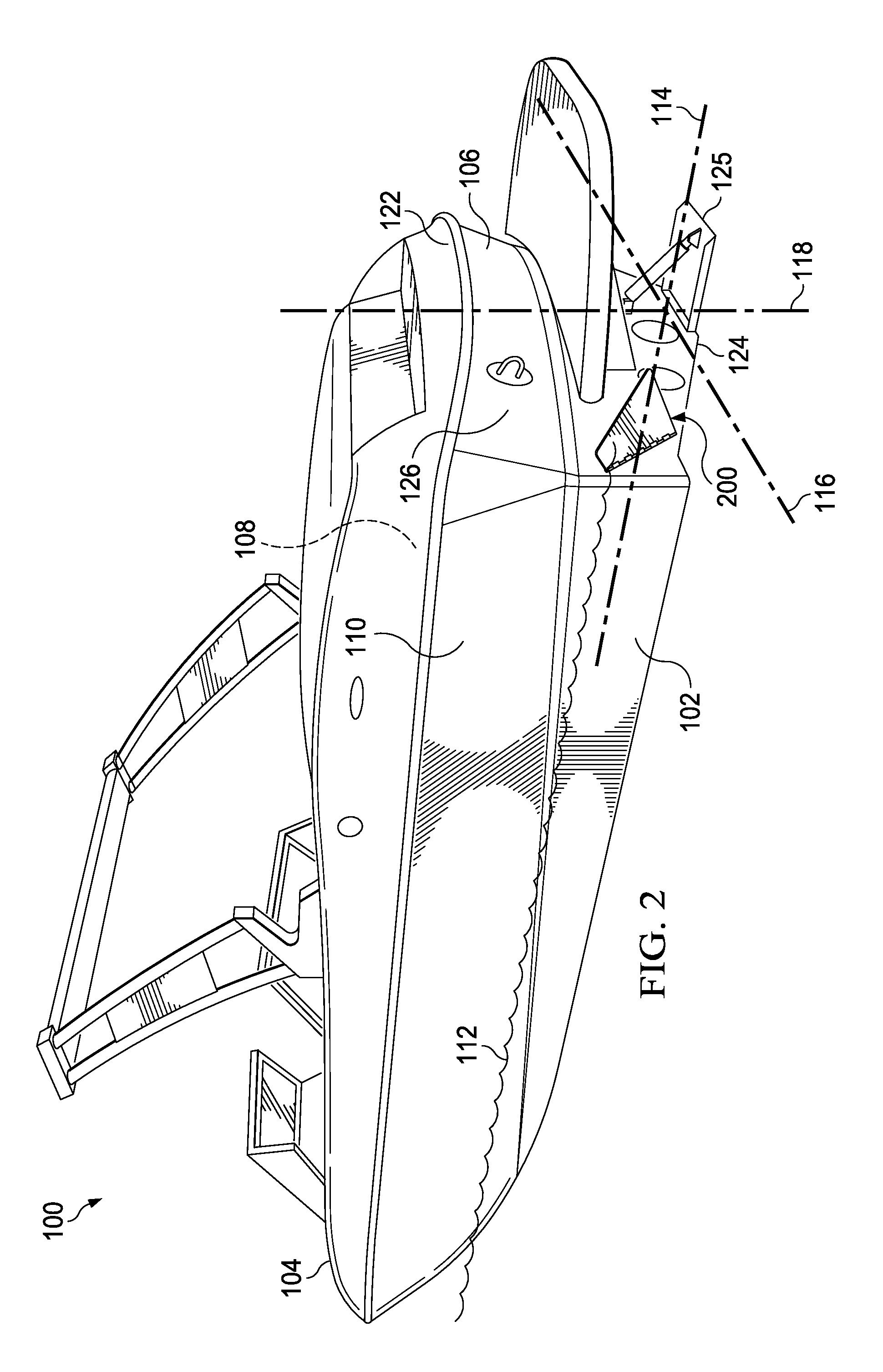
[0037]To facilitate the understanding of this disclosure, a number of marine terms are defined below. Terms defined herein have meanings as commonly understood by a person of ordinary skill in the areas relevant to the present disclosure. “Starboard” refers to the right-hand, or driver's, side of the boat. “Port” refers to the left-hand, or passenger's, side of the boat. “Bow” refers to the front of the boat. “Transom” and “stern” refer to the rear of the boat. Terms such as “a”, “an”, and “the” are not intended to refer to only a singular entity, but include t...


PUM


Abstract

A boat comprising a wake shaping system comprising starboard and port wake shaping devices located aft of the transom, each wake shaping plate device comprising a first mounting portion coupled to the transom and a second plate portion pivotably coupled to the first mounting portion. A portion of the second plate potion of each wake shaping device is operable to pivot approximately 90° between a first, non-deployed position behind the transom and a second, deployed position extending below the transom. When the portion of the second portion of the starboard wake shaping device is in the deployed position, a port wakesurf wake is created. When the portion of the second portion of the port of the wake shaping device is in the deployed position, a starboard wakesurf wake is created. When neither wake shaping device is deployed, a symmetrical wakeboard wake is created.

Description

RELATED APPLICATION[0001]This application is a continuation application of U.S. application Ser. No. 14 / 506,039 which was filed on Oct. 3, 2014, the contents of which are incorporated herein by reference as if set forth in full.TECHNICAL FIELD[0002]The present disclosure generally relates to a wake shaping system for a boat, and more particularly, to a wake shaping system for wakesurfing behind an inboard boat.BACKGROUND[0003]During the first half of the twentieth century, waterskiing emerged as a popular recreational activity, allowing individuals to ski behind a boat on a lake, river, or ocean. The first waterski boats, however, were wooden boats that produced large wakes because of the weight of the boats. In search of a smaller wake, which is advantageous for waterskiing, the first fiberglass inboard waterski boat was designed and built in the early 1960s. Throughout the 1970s, 1980s, 1990s, and today, inboard ski boat manufacturers continue to refine ski boat designs to produce...

Claims


Application Information

Patent Timeline
Patent Type & Authority Patents(United States)
IPC IPC(8): B63B35/85B63B35/73B63B1/32
CPCB63B35/85B63B35/73B63B1/32B63B2035/855B63B39/061B63B34/70B63B34/75Y02T70/10B63B1/20
Inventor BRENDEL, MICHAEL HARDY
Owner MB SPORTS
Why Eureka
Try Eureka