
Adaptor pallet

a technology of adaptors and pallets, applied in the field of adaptor pallets, can solve the problems of inconvenient and laborious dollies, and long operation duration, and achieve the effect of reducing the number of dollies and requiring a thorough and tedious trussing up

Active Publication Date: 2015-10-20
K HARTWALL OY AB
View PDF18 Cites 5 Cited by
  • Summary
  • Abstract
  • Description
  • Claims
  • Application Information

AI Technical Summary

Benefits of technology

[0007]Considerable benefits are gained with aid of the present invention. Due to the novel releasable locking structure combined with a separate pivoting attachment between the locking plate and the lifting structure of the pallet, the frames of the dolly may be secured to the pallet without reaching down to negotiate a ramp with a combined pivoting and locking guides according to the prior art. On the other hand, the proposed locking structure may be provided without separate manipulation means, whereby the structure is very robust and light.
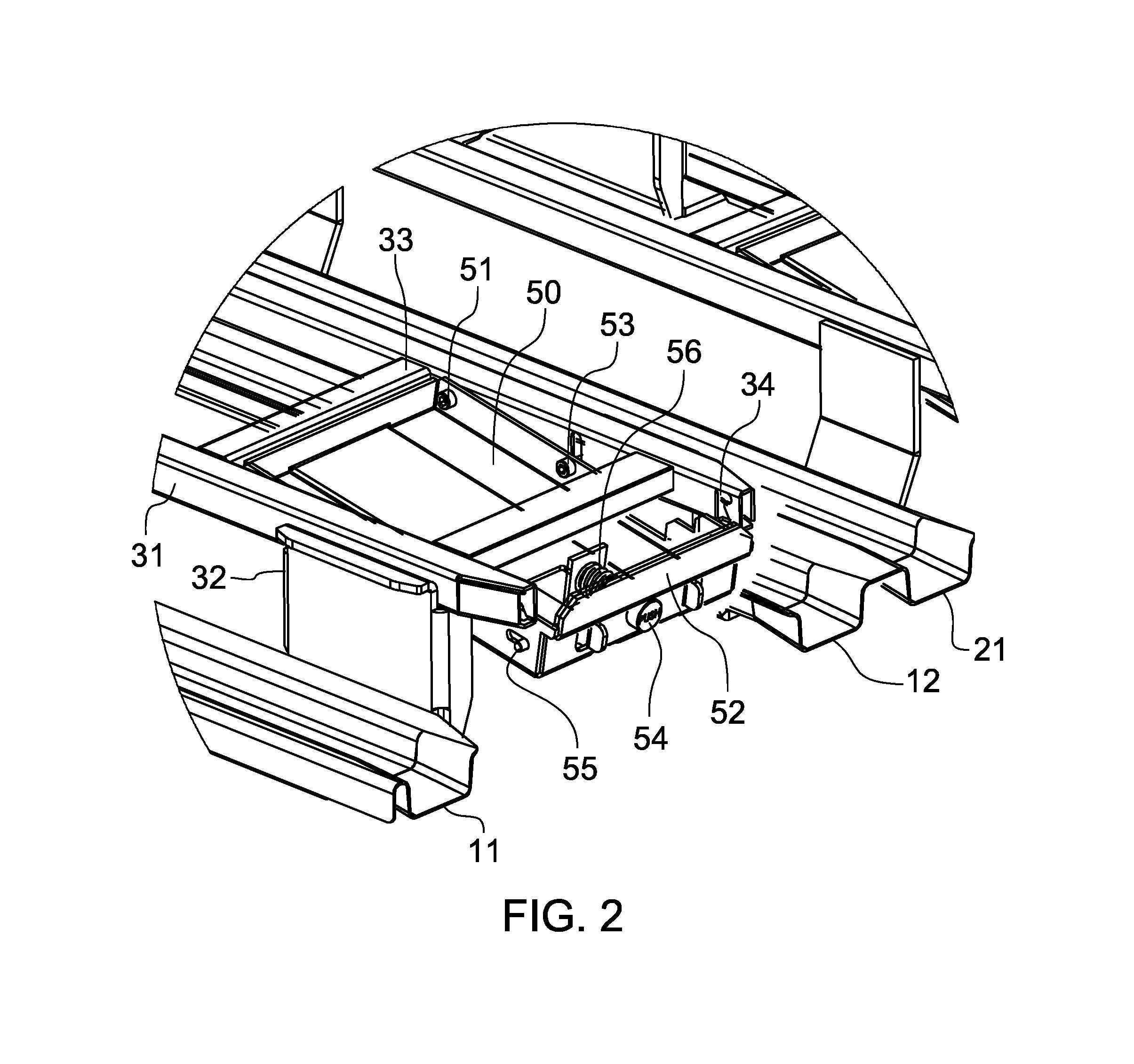
[0008]According to one embodiment, the means for releasably affixing the locking plate into a horizontal position comprises a latch which is suspended to the locking plate and configured to slide in and out of a slot arranged in a longitudinal beam of the lifting structure for securing the locking plate into and releasing it from the horizontal locking position. The suspension makes it possible to bias the latch such that it may be released from the locking position by operating the latch directly by foot, for example. As the latch is suspended in relation to the locking plate, no external manipulation means are necessary.
[0009]According to one embodiment, the rotation joint between the locking plate and the lifting structure of the pallet is provided to the end of the locking plate farthest from the loading end of the adaptor pallet, whereas the latch is provided to the end of the locking plate nearest to the loading end of the adaptor pallet and opposing the rotation joint. With such a configuration the locking plate is adapted to pivot such that the locking protrusion of the locking plate can pivot down at the loading end of the pallet for allowing dollies to be loaded onto the pallet. As a result, the locking plates may be locked into a horizontal locking position by lifting them up from the loading end. This yields a particularly advantageous effect of being able to lock the dollies into place with one lifting motion by inserting the lifting forks of a forklift under the lifting structures and lifting said forks, whereby the locking plates automatically snap into locking position.

Problems solved by technology

If a trailer is loaded dolly by dolly, the long duration of the operation consumes valuable docking time not to mention inflicted gratuitous vehicle idle time.
Also, when transported individually, the dollies require thorough and tedious trussing up to prevent unintended movement within the load space.
While the open end type adaptor pallet is advantageous in that it is easy to use, the manipulation system for toggling the locking elements may be quite complex making the adaptor pallet expensive to make and buy as well as heavy and eventually vulnerable to failure.
The second type of adaptor pallets is indeed very light and robust but it suffers from awkward user interface in that the locking ramp must be operated by hand, wherein a combined rotation and lifting motion is required to negotiate the ramp.

Method used


Image

  • Adaptor pallet
  • Adaptor pallet
  • Adaptor pallet

Examples


Embodiment Construction

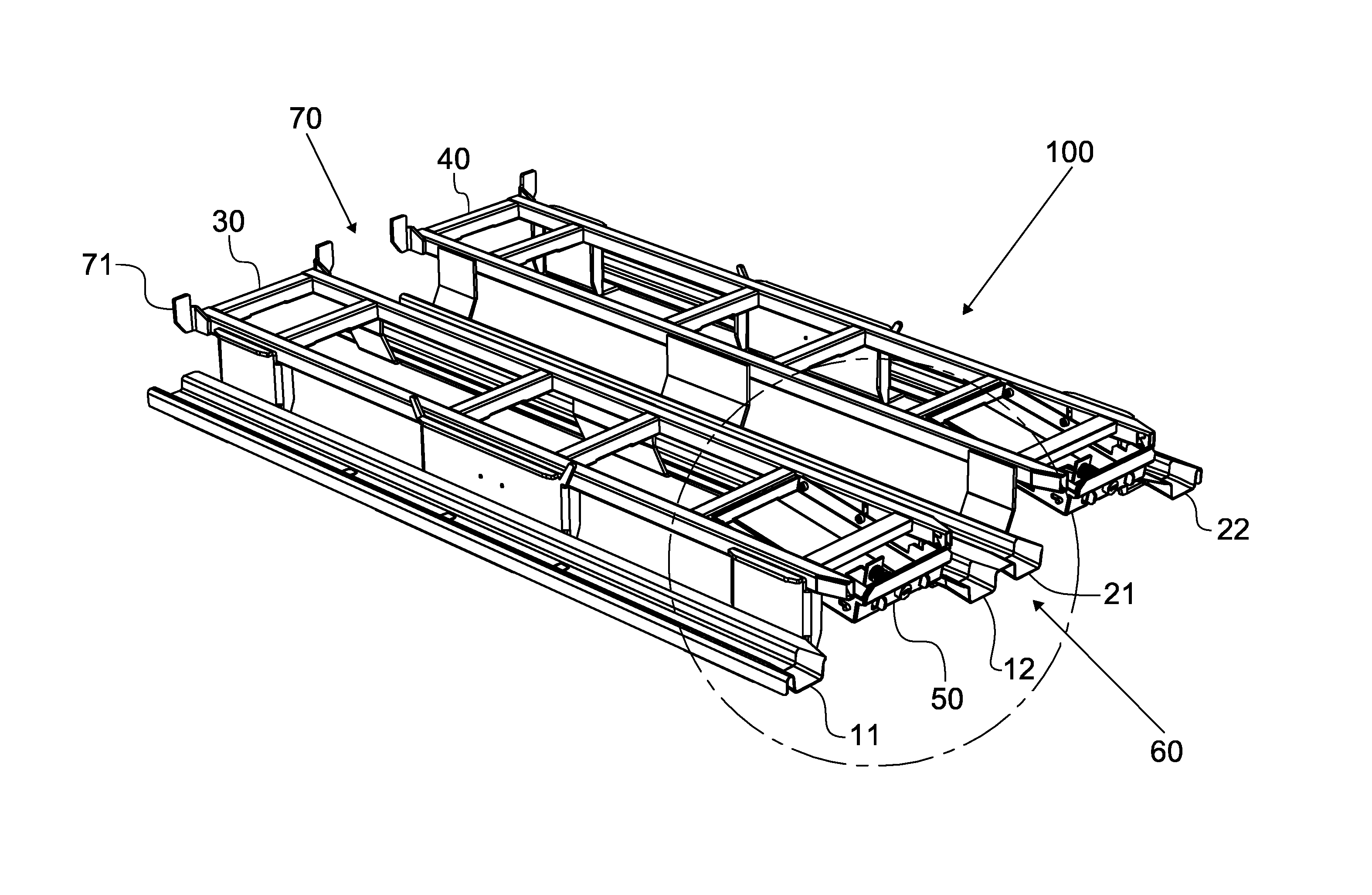
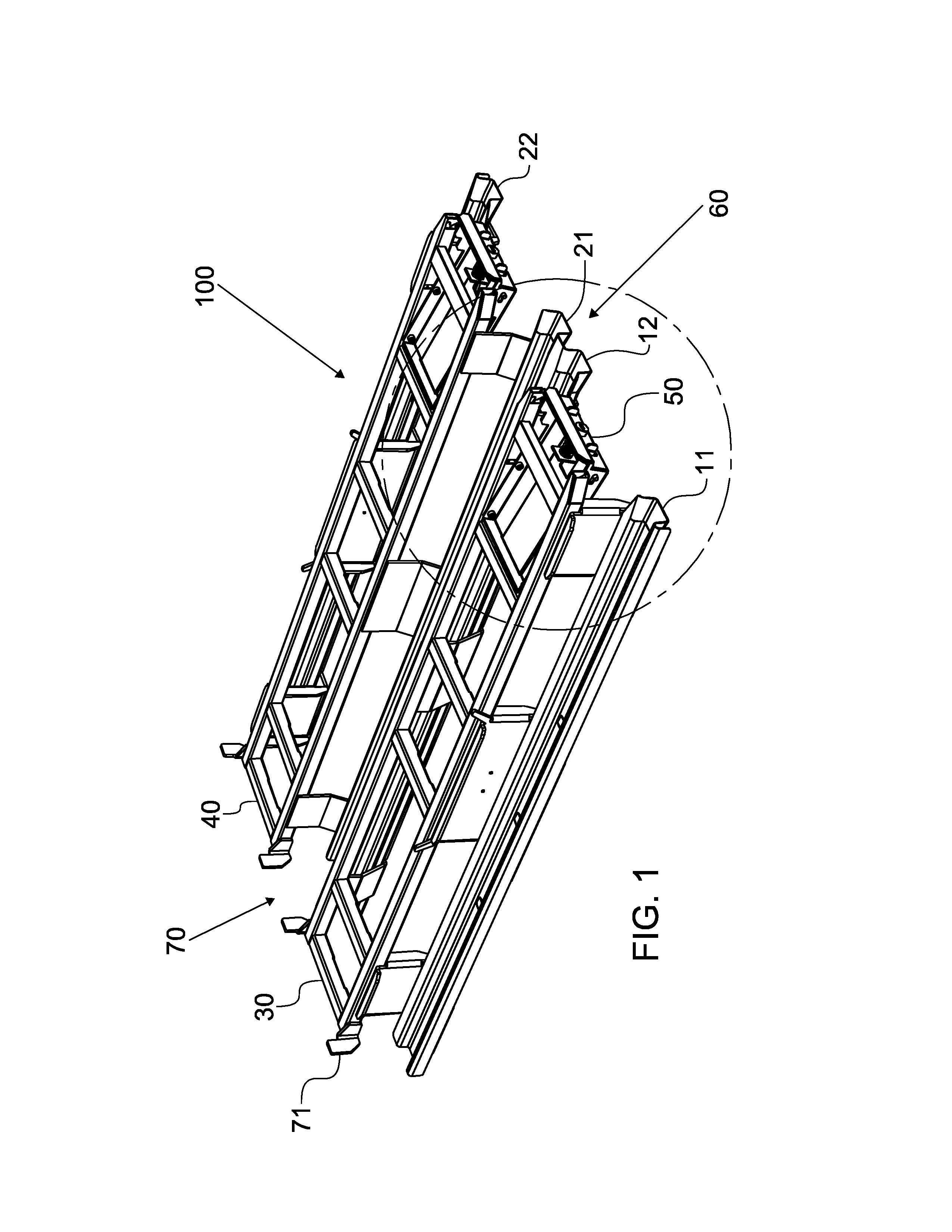
[0018]FIG. 1 shows an overview of an empty adaptor pallet 100 according to one embodiment in an open, i.e. not locked, position. The adaptor pallet 100 includes a first set of parallel tracks 11, 12 for receiving the wheels of a first plurality of dollies. The tracks define a longitudinal direction in which the dollies are intended to be loaded and unloaded. The tracks 11, 12 are formed as grooves having a cross-section resembling the letter U which provides adequate lateral support for the wheels of the dolly. The deepness of the grooves of the tracks 11, 12 also aids in guiding the wheels thereby reducing their tendency to turn sideways to the longitudinal direction.

[0019]A first lifting structure 30 is arranged between the first set of tracks 11, 12 at an elevated level from the tracks 11, 12. The lifting structure 30 is provided in the form an upwardly extending tunnel for receiving the lifting forks of a fork-lift. FIG. 2 shows the construction of the lifting structure 30 in de...


PUM


Abstract

The adaptor pallet includes two sets of parallel tracks, a lifting structure connecting the tracks at an elevated level, a loading end for introducing dollies to the adapter pallet, and a closed end including a stopper for limiting the movement of dollies. The adaptor pallet further includes a locking plate which is rotatably connected to the lifting structure at one end, while another end of the locking plate includes a stopper protrusion and a member for releasably affixing the locking plate into a horizontal position such that the stopper protrusion limits the movement of the dollies at the loading end of the adaptor pallet, wherein the locking plate is releasable from the horizontal position into an angled position for opening the loading end of the adaptor pallet.

Description

FIELD OF THE INVENTION[0001]The present invention relates to an adaptor pallet for transporting and storing a plurality of wheeled dollies.BACKGROUND ART[0002]Goods of relatively small size are typically transported using wheeled dollies which are platforms mounted on wheels or castors. Goods are stored in containers that fit into the receptive platform. Upon transportation or temporary storage, the usually boxlike containers are stacked onto dollies whose wheels enable easy handling by hand. The shape and size of the dollies are usually standardized to conform advantageously to industrial container models. While the dollies may be moved about by hand, there is also a need to transport a plurality of dollies at once. Such a need occurs e.g. when loading or unloading a trailer or a lorry. If a trailer is loaded dolly by dolly, the long duration of the operation consumes valuable docking time not to mention inflicted gratuitous vehicle idle time. Also, when transported individually, t...

Claims


Application Information

Patent Timeline
Patent Type & Authority Patents(United States)
IPC IPC(8): B65D85/68B65D19/00B65D19/44
CPCB65D85/68B65D19/0095B65D19/44B65D2519/0096B65D2519/00273B65D2519/00293B65D2519/00323B65D2519/00333B65D2519/00815B65D2585/686
Inventor GRONHOLM, JACKRANINEN, JUSSI
Owner K HARTWALL OY AB
Learn More