Supercharge Your Innovation With Domain-Expert AI Agents!

Imaging device, and imaging method

a technology of imaging device and optical magnification, which is applied in the field of imaging device and imaging method, can solve the problems of difficult to perform the operation of changing the optical magnification of the ovf, and it is not easy to freely perform the switching operation of the optical viewfinder

Inactive Publication Date: 2015-10-20
FUJIFILM CORP
View PDF4 Cites 0 Cited by
  • Summary
  • Abstract
  • Description
  • Claims
  • Application Information

AI Technical Summary

Benefits of technology

[0026]The present invention makes it possible to freely perform a switching operation for determining which of an optical image of a photographic subject and a captured image of the photographic subject is to be led to an eyepiece part of a finder and a switching operation of an optical magnification of the finder while looking through the eyepiece part.

Problems solved by technology

However, it is not easy to freely perform a switching operation of an optical viewfinder (also called “OVF” hereinafter) and an electronic viewfinder (also called “EVF” hereinafter) and a magnification varying operation of the optical viewfinder (OVF) while looking through an eyepiece part.
However, when the EVF is switched to the OVF, it is difficult to perform an operation of changing an optical magnification of the OVF (finder magnification varying operation) while looking through the eyepiece part.

Method used


Image

  • Imaging device, and imaging method
  • Imaging device, and imaging method
  • Imaging device, and imaging method

Examples


first example

Finder Operation of First Example

[0107]FIG. 10 is a flowchart illustrating a flow of finder control processing corresponding to a lever operation of a first example. This processing is executed according to a program by the main CPU 251 of the camera body 200.

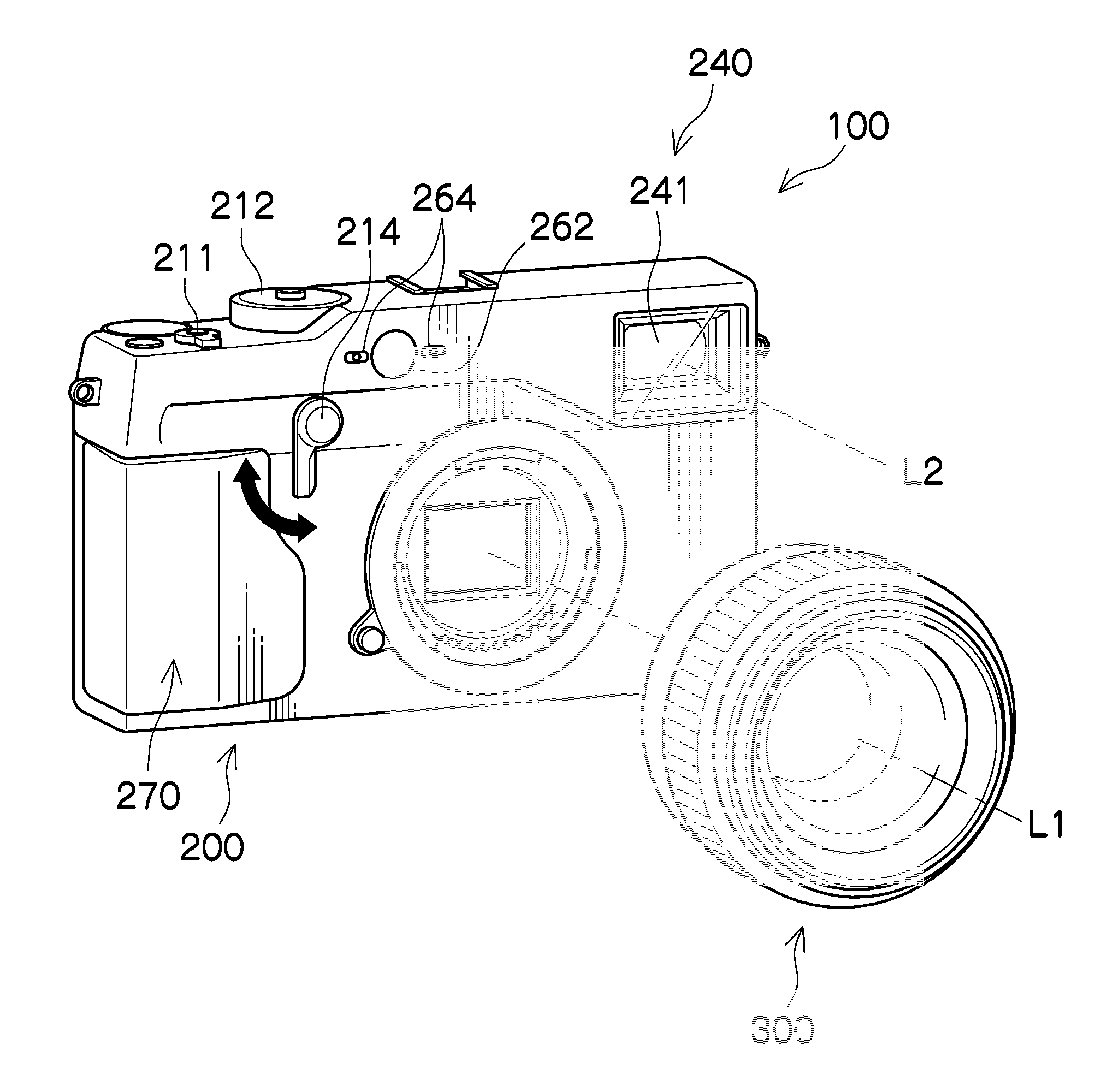
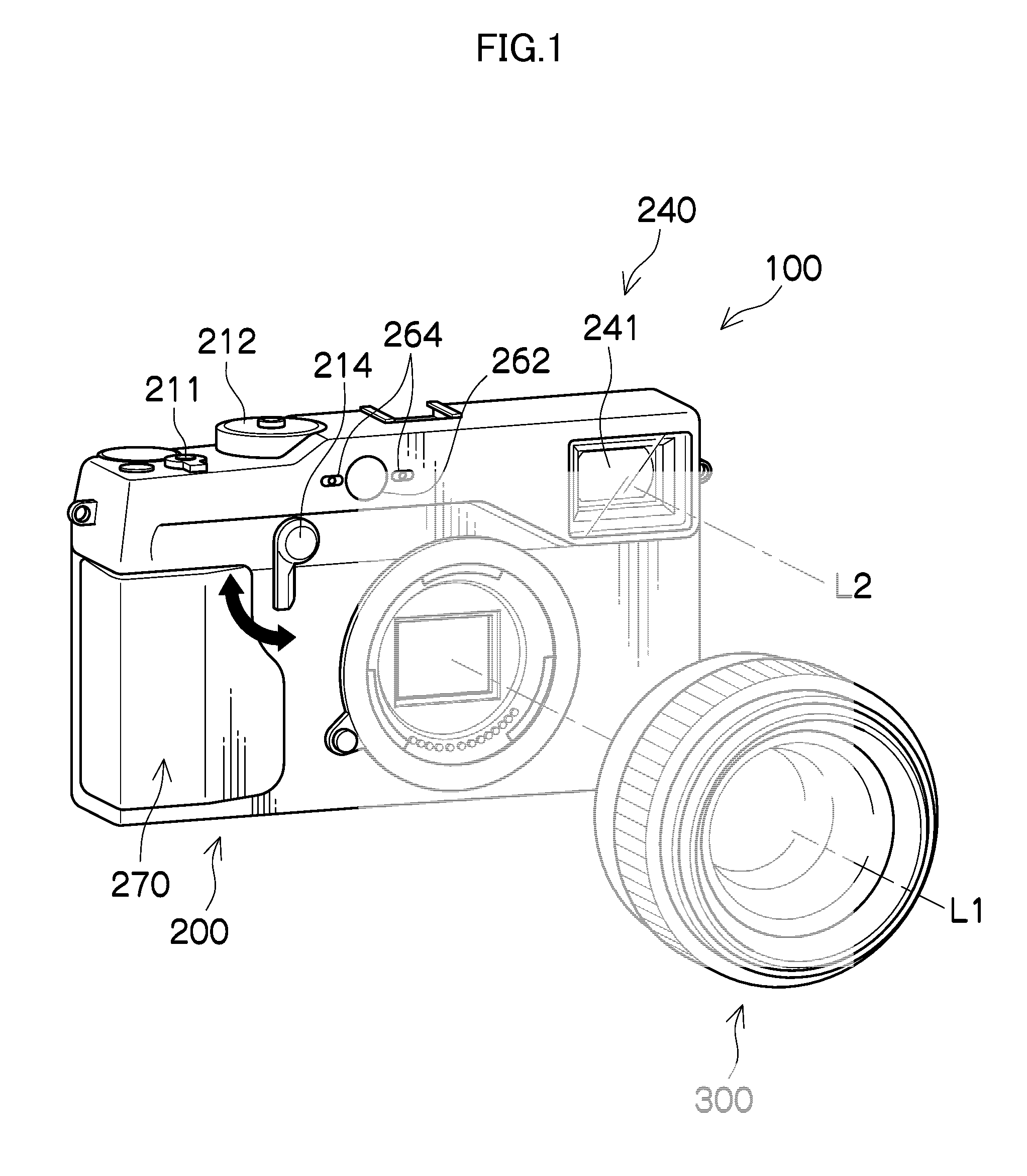
[0108]First, the finder 240 is initialized to the OVF (optical viewfinder) state (step S2), an OVF flag is set at “1” (OVF) (step S4), and the optical magnification (OVF magnification) of the finder 240 is automatically set on the basis of the focal distance of the interchangeable lens 300 (step S6). In this example, the finder variable magnification lens 244 is set at the entering position in the case that the focal distance of the interchangeable lens 300 is equal to or longer than a prescribed value (30 mm in this example), and the finder variable magnification lens 244 is set at the withdrawn position in the case that the focal distance of the interchangeable lens 300 is shorter than the prescribed value.

[0109]Whether or no...

second example

Finder Operation of Second Example

[0112]FIG. 11 is a flowchart illustrating a flow of finder control processing corresponding to the operation of the second example. This processing is executed according to the program by the main CPU 251 of the camera body 200.

[0113]Steps S32-S36 are similar to steps S2-S6 of the first example illustrated in FIG. 10, and descriptions are omitted.

[0114]Whether or not the finder operation lever 214 is operated is determined (step S38), and in the case that the operation is performed, whether or not the finder operation lever 214 is operated for a first number of times is determined (step S40). That is, whether or not the operation of repeatedly positioning the finder operation lever 214 at the second position at a time interval shorter than a fixed time interval (1 second for instance) is performed for the first number of times (1 time for instance) is determined. In the case that the finder operation lever 214 is operated for the first number of tim...


PUM


Abstract

According to the preset invention, an optical viewfinder state in which an optical image of a photographic subject can be observed at an eyepiece part of a finder and an electronic viewfinder state in which a captured image of the photographic subject can be observed at the eyepiece part of the finder are switched when a first operation is carried out with a finger by an operation device, and a magnification (optical magnification) of a first finder optical system of the finder is changed when a second operation is carried out with a finger by the operation device in the optical viewfinder state. Thus, a user can perform photographing while freely observing the photographic subject by an operation of switching the finder (first operation) and an operation of changing the optical magnification of the finder (second operation) while looking through the finder.

Description

CROSS-REFERENCE TO RELATED APPLICATIONS[0001]This application is a Continuation of PCT International Application No. PCT / JP2012 / 083225 filed on Dec. 21, 2012, which claims priority under 35 U.S.C. §119(a) to Japanese Patent Application No. 2012-89494 filed on Apr. 10, 2012. Each of the above application(s) is hereby expressly incorporated by reference, in its entirety, into the present application.BACKGROUND OF THE INVENTION[0002]1. Field of the Invention[0003]The present invention relates to an imaging device and an imaging method, and in particular, relates to an imaging device and an imaging method that make it possible to freely perform a switching operation for determining which of an optical image of a photographic subject and a captured image of the photographic subject is to be led to an eyepiece part of a finder and a switching operation of an optical magnification of the finder while looking through the eyepiece part.[0004]2. Description of the Related Art[0005]PTL 1 (Japa...

Claims


Application Information

Patent Timeline
Patent Type & Authority Patents(United States)
IPC IPC(8): H04N5/222H04N5/225H04N5/232G03B13/06G03B17/20
CPCG03B13/06G03B17/20H04N5/2251H04N5/2252H04N5/2254H04N5/23216H04N5/23245H04N5/23293H04N5/23296H04N23/55H04N23/672H04N23/673H04N23/635H04N23/69H04N23/667H04N23/51H04N23/62
Inventor JOGETSU, TADASHIOKUBO, TAKESHI
Owner FUJIFILM CORP
Features
  • R&D
  • Intellectual Property
  • Life Sciences
  • Materials
  • Tech Scout
  • Unparalleled Data Quality
  • Higher Quality Content
  • 60% Fewer Hallucinations
Learn More