Digital documenting ophthalmoscope

a digital and ophthalmoscope technology, applied in the field of medical diagnostic instruments, can solve the problems of high power consumption of light sources, difficult packaging, and limitations of commercial eye viewing devices for retinal viewing, and achieve the effect of low input power and low cos

Inactive Publication Date: 2008-04-29
WELCH ALLYN INC
View PDF247 Cites 111 Cited by
  • Summary
  • Abstract
  • Description
  • Claims
  • Application Information

AI Technical Summary

Benefits of technology

[0007]According to its major aspects and broadly stated, the present invention is a low input power, low cost eye viewing device for use in viewing a retina and for obtaining electronic images thereof.

Problems solved by technology

Commercially available eye viewing devices for use in retinal viewing have been observed to exhibit numerous limitations.
The substantial light losses inherent with this design requires that a large, high powered light source be incorporated in the device for the device to satisfactorily illuminate a retina.
High powered light sources, in general, are difficult to package, consume excessive amounts of electrical input power, and produce large amounts of heat and unwanted light such as glare.
This makes indirect ophthalmoscopes especially susceptible to glare problems attributable to incident light rays being reflected from outer eye structures such as the iris, cornea and sclera.
Additionally, because there is a limit to the level of illumination which is safe to introduce into they eye, high powered illumination systems never fully compensate for the losses introduced by a beamsplitter.
However, retinal viewing cameras, in general, are expensive, typically require pupil dilation for retinal viewing, and typically require operation by a highly skilled and trained camera operator and these cameras are also large, bulky, and consume excessive space.
Further, they frequently illuminate with infrared illumination only during “aiming” which makes the views during aiming unsuitable for diagnosis.

Method used


Image

  • Digital documenting ophthalmoscope
  • Digital documenting ophthalmoscope
  • Digital documenting ophthalmoscope

Examples


Embodiment Construction

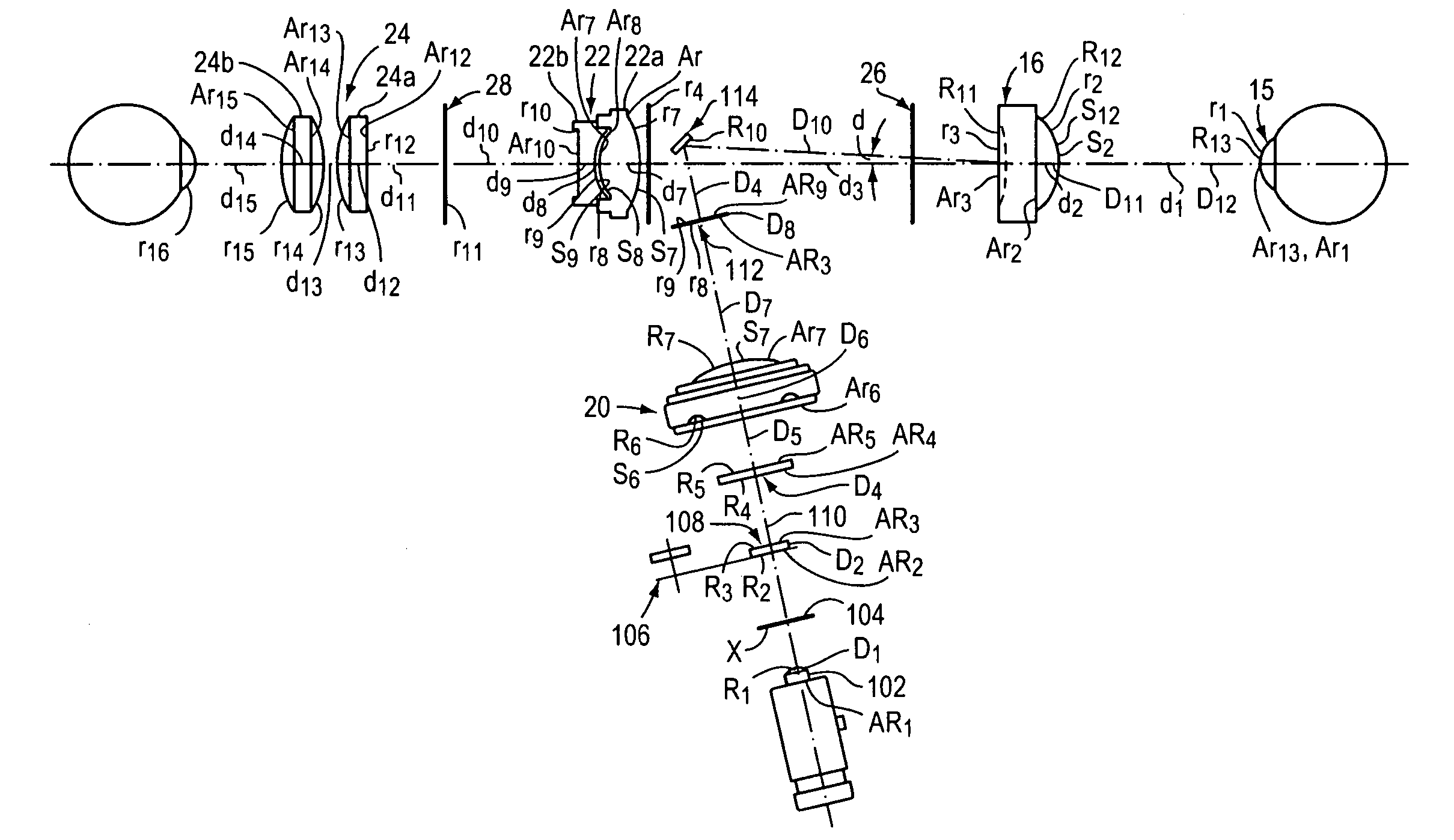
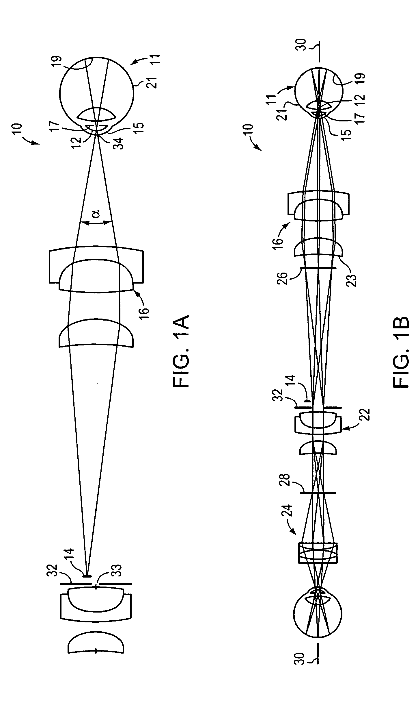
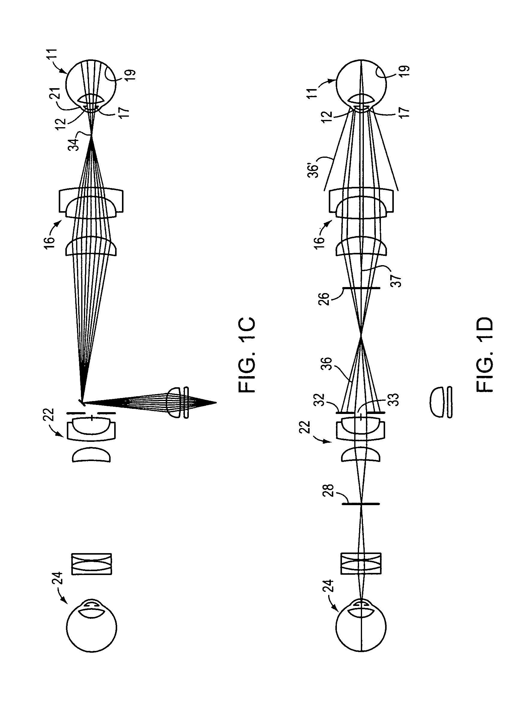
[0039]An exemplary embodiment of an eye viewing device according to the invention is described with reference to FIGS. 1A-1E. Eye viewing device 10 includes an illumination system, the operation of which is described mainly with reference to FIG. 1A, and an imaging system, the operation of which is described mainly with reference to FIG. 1B.

[0040]The device of FIGS. 1A-1E is especially well suited for use in viewing a retina through an undilated pupil. Small diameter undilated pupils present numerous challenges to viewing retinal images. Small diameter undilated pupils tend to inhibit the transmission of both incident light directed toward a retina and reflected light corresponding to a retinal image. Furthermore, light that is directed into a pupil and that is blocked from entry into a pupil by highly reflective surfaces of outer eye structures such as the iris and sclera tends to be reflected into a viewing system as glare. As will be explained herein below, the device of FIGS. 1A...


PUM


Abstract

The invention is an eye viewing device having an eyepiece at an observer end thereof and an imaging element at an observation port thereof. Light that is reflected from an imaged eye of a patient is provided to either or both of the eyepiece and the imaging element. A practitioner can view the imaged eye, and can sequentially image the same region of the imaged eye for recording, documentation, and / or analysis.

Description

CROSS-REFERENCE TO RELATED APPLICATIONS[0001]This application claims priority to and the benefit of now abandoned U.S. Provisional Patent Application Ser. No. 60 / 515,136, filed Oct. 28, 2003, which application is incorporated herein by reference in its entirety. This application is related to U.S. patent application Ser. No. 09 / 862,636 entitled “Eye Viewing Device Comprising Eyepiece and Video Capture Optics” filed May 22, 2001, which is a Continuation-in-part of U.S. patent application Ser. No. 09 / 783,481 entitled “Eye Viewing Device for Retinal Viewing Through Undilated Pupil” filed Feb. 14, 2001, which is a Continuation-in-part of U.S. patent application Ser. No. 09 / 444,161 entitled “Eye Viewing Device for Retinal Viewing Through Undilated Pupil” filed Nov. 22, 1999, which is a Continuation-in-part of U.S. patent application Ser. No. 09 / 198,545 entitled “Ophthalmoscope Comprising Defocused Light Source” filed Nov. 24, 1998, which issued May 23, 2000 as U.S. Pat. No. 6,065,837. Ea...

Claims


Application Information

Patent Timeline
Patent Type & Authority Patents(United States)
IPC IPC(8): A61B3/10A61B3/12A61B3/13A61B3/14
CPCA61B3/158
Inventor GOLDFAIN, ERVINSALVATI, JONFALLAT, DAVIDWAWRO, MARCIAMCMAHON, MICHAEL
Owner WELCH ALLYN INC
Why Eureka
Try Eureka