Hydraulic variable-speed transmission device

A transmission and hydraulic speed change technology, applied in transmission, fluid transmission, transmission control, etc., can solve the problems of high energy consumption, power energy conversion efficiency is not brought into full play, and mechanical transmission efficiency is low. The effect of strong overload capacity, reducing input power and improving conversion rate

Inactive Publication Date: 2012-10-24
HUNAN CHANGZHONG MACHINERY
View PDF8 Cites 13 Cited by
  • Summary
  • Abstract
  • Description
  • Claims
  • Application Information

AI Technical Summary

Problems solved by technology

[0003] In the process of realizing the present invention, the inventor has found that the prior art has at least the following problems: the speed change of the automobile engine and the speed change of the motor in the prior art all consume a large amount of energy in the process of speed change and transmission of power, and the power energy The conversion efficiency has not been brought into full play, and the mechanical transmission efficiency is low

Method used


Image

  • Hydraulic variable-speed transmission device
  • Hydraulic variable-speed transmission device

Examples


Embodiment 1

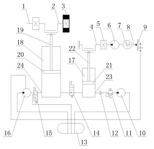
[0023] This embodiment provides a hydraulic transmission device, see figure 1 , the transmission device includes: a large hydraulic cylinder 18, a small hydraulic cylinder 17, a hydraulic oil tank 13, a stepless speed regulating device 9 and a drive motor 7, the large hydraulic cylinder 18 and the small hydraulic cylinder 17 are two mutually independent cylinder bodies, the large The hydraulic cylinder 18 and the small hydraulic cylinder 17 are connected by an oil pipeline, and a two-position two-way solenoid valve 14 is arranged on the oil pipeline connecting the large hydraulic cylinder 18 and the small hydraulic cylinder 17. The large hydraulic cylinder 18 and the small hydraulic cylinder 17 are communicated with the hydraulic oil tank 13 through the oil pipeline respectively.

[0024] A large piston 20 is arranged in the large hydraulic cylinder 18, and the large piston 20 is connected with the large piston crank mechanism 2 through the large piston connecting rod 19. One ...

Embodiment 2

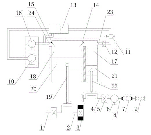
[0036] This embodiment provides a hydraulic transmission device, see figure 2 , the transmission device includes: a large hydraulic cylinder 18, a small hydraulic cylinder 17, a hydraulic oil tank 13, a stepless speed regulating device 9 and a drive motor 7, the large hydraulic cylinder 18 and the small hydraulic cylinder 17 are an integral cylinder with a partition Divided into. A communication hole is provided on the partition between the large hydraulic cylinder 18 and the small hydraulic cylinder 17, and a two-position two-way solenoid valve 14 is arranged at the communication hole, and the large hydraulic cylinder 18 and the small hydraulic cylinder 17 pass through the oil pipeline respectively. It communicates with the hydraulic oil tank 13.

[0037] A large piston 20 is arranged in the large hydraulic cylinder 18, and the large piston 20 is connected with the large piston crank mechanism 2 through the large piston connecting rod 19. One end of the large piston crank m...


PUM


Abstract

The invention discloses a hydraulic variable-speed transmission device. The transmission device comprises a large hydraulic cylinder, a small hydraulic cylinder, a hydraulic oil tank, an electrodeless speed adjusting device and a driving motor, wherein the large hydraulic cylinder and the small hydraulic cylinder are communicated with each other through an oil conveying pipeline; a two-position two-way solenoid valve is arranged on the oil conveying pipeline between the large hydraulic cylinder and the small hydraulic cylinder; the large hydraulic cylinder and the small hydraulic cylinder are respectively communicated with the hydraulic oil tank through the oil conveying pipeline; when the driving motor works, a main oil pump is driven to work by hydraulic pressure for transmission, a small-piston crankshaft is driven to operate by a variable-speed transmission output device, and the driving motor simultaneously drives a small-piston input oil pump and a large-piston output oil pump to work through a shaft coupler and the electrodeless speed-adjusting device. The hydraulic variable-speed transmission device disclosed by the invention is provided with the advanced electrodeless speed-adjusting device, and the speed and the pressure of the oil amount of each hydraulic pump can be controlled according to programmed work procedures, thereby realizing the aim of speed and pressure adjustment; and particularly, a Pascal hydraulic principle is utilized to improve the conversion rate of source power by times.

Description

technical field [0001] The present invention relates to the field of speed change equipment, in particular to a hydraulic speed change transmission device, which is mainly used in stepless automatic transmissions of modern industrial automation program control, and can also change the program control mode (industrial automation adopts PLC control, and automobiles can use single-chip microcomputer fixed programs) When used in the automotive industry, variable speed transmission is realized by adjusting the conversion of hydraulic pressure and energy. Background technique [0002] Almost all existing transmission devices use mechanical transmission gear shifting to transmit output power. For vehicles: traditional hydraulic automatic transmissions automatically change gears according to changes in vehicle speed and throttle opening. The gear control method is to convert the vehicle speed and throttle opening signal into control oil pressure through mechanical means, and add the...

Claims


Application Information

Patent Timeline
Patent Type & Authority Applications(China)
IPC IPC(8): F16H47/02F16H61/435
Inventor 肖谋廷许鹏蔡小艳陈春莲
Owner HUNAN CHANGZHONG MACHINERY
Why Eureka
Try Eureka