Pulse width modulation inverter circuit and control method thereof

a pulse width modulation and inverter circuit technology, applied in the direction of electric variable regulation, process and machine control, instruments, etc., can solve the problems of low output efficiency, high input voltage but, low output efficiency, etc., and achieve the effect of increasing the frequency of oscillation signals, reducing and increasing the pulse width of the pulse width modulation signal

Inactive Publication Date: 2007-07-10
BEYOND INNOVATION TECH
View PDF13 Cites 14 Cited by
  • Summary
  • Abstract
  • Description
  • Claims
  • Application Information

AI Technical Summary

Benefits of technology

[0013]Accordingly, the present invention is directed to a pulse width modulation inverter circuit. According to the voltage input to the direct current (DC) source power, the circuit adjusts the pulse width of the pulse signal outputted from the power switch driver of the circuit to avoid high input voltage but low output efficiency in the circuit.
[0019]According to the inverter circuit in an embodiment of the present invention, when the feedback control signal outputted from the detecting unit becomes smaller, the operational frequency of the oscillation signal outputted from the oscillator is also reduced. When the feedback control signal outputted from the detecting unit becomes larger, the operational frequency of the oscillation signal outputted from the oscillator is increased.
[0020]According to the inverter circuit in an embodiment of the present invention, when the voltage of the DC power source becomes larger, the pulse width of the pulse width modulation signal is reduced, and when the voltage of the DC power source becomes smaller, the pulse width of the pulse width modulation signal is increased.
[0026]According to the control method of the pulse width modulation inverter circuit of an embodiment of the present invention, when the AC signal through the load becomes smaller, the frequency of oscillation signal is reduced, and when the AC signal through the load becomes larger, the frequency of oscillation signal is increased.
[0027]According to the control method of the pulse width modulation inverter circuit of an embodiment of the present invention, when the voltage of the DC power source becomes larger, the pulse width of the pulse width modulation signal is reduced, and when the voltage of the DC power source becomes smaller, the pulse width of the pulse width modulation signal is increased.
[0028]Accordingly, the pulse width modulation inverter circuit of the present invention adjusts the pulse width of the pulse width signal outputted from the pulse width modulation power switch driving circuit according to the voltage of the DC power source. When the voltage of the DC power source is larger, the pulse width of the pulse signal is adjusted to reduce the input power of the load. The oscillation frequency of the resonance tank seriously shifting away from the resonant frequency can be avoided and the decline of the efficiency of the circuit can also be eliminated.

Problems solved by technology

According to the voltage input to the direct current (DC) source power, the circuit adjusts the pulse width of the pulse signal outputted from the power switch driver of the circuit to avoid high input voltage but low output efficiency in the circuit.
According to the voltage input to the DC power source, the pulse width of the pulse width modulation signal is adjusted to avoid high input voltage but low output efficiency.

Method used


Image

  • Pulse width modulation inverter circuit and control method thereof
  • Pulse width modulation inverter circuit and control method thereof
  • Pulse width modulation inverter circuit and control method thereof

Examples


Embodiment Construction

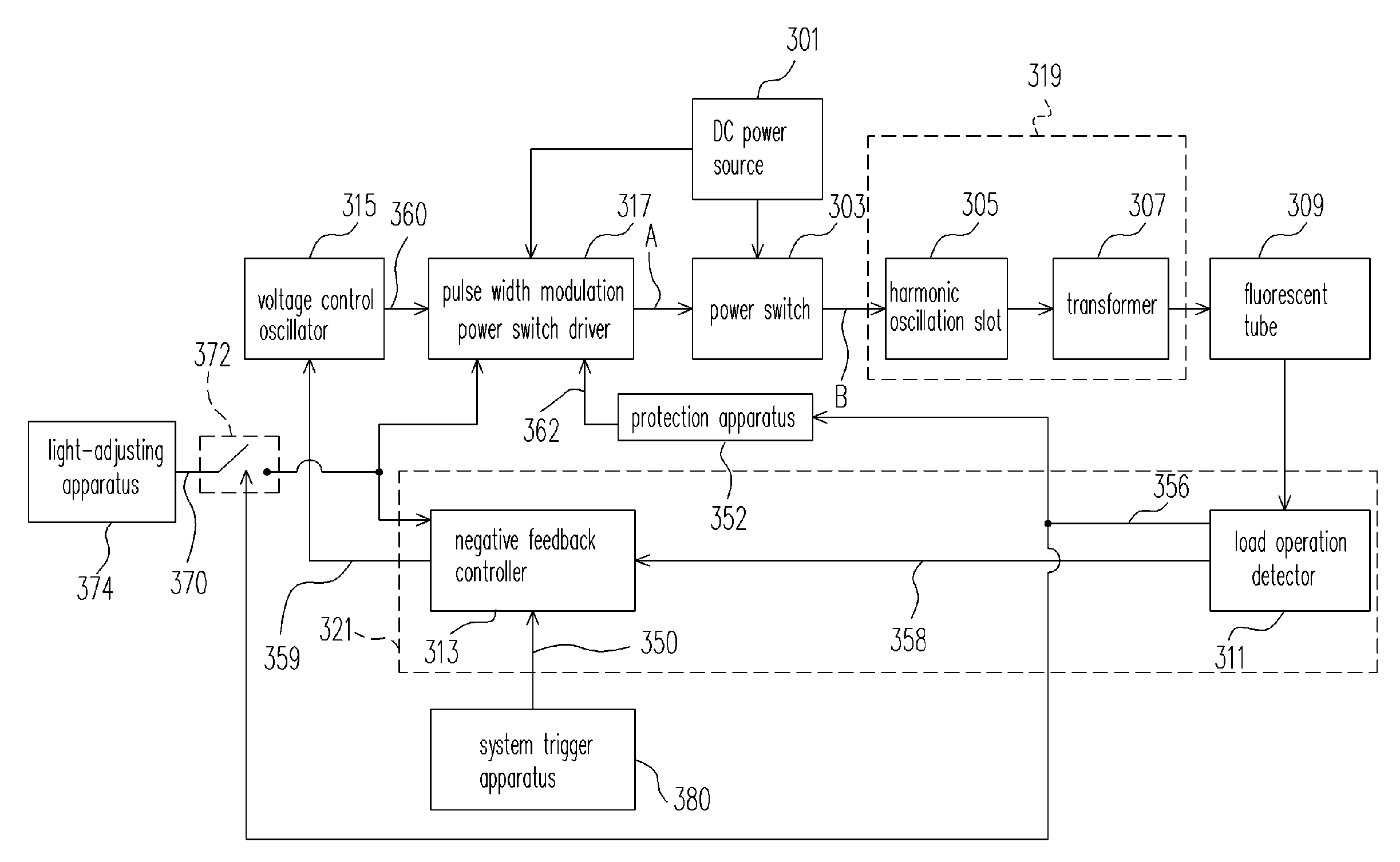
[0037]FIG. 3 is a circuit block diagram showing an inverter circuit according to an embodiment of the present invention. Referring to FIG. 3, different from the traditional inverter circuit, the embodiment of the present invention replaces the fixed pulse width power switch driver of the traditional circuit with the pulse width modulation power switch driver 317. The pulse width modulation power switch driver 317 receives the voltage from the DC power source 301 to determine the output pulse width.

[0038]When the circuit starts operation, after receiving the voltage of the DC power source 301, the pulse width modulation power switch driver 317 outputs the pulse width modulation signal according to the voltage of the DC power source 301. The power switch 303 determines its own turn-on time period according to the pulse width of the pulse width modulation signal. The power switch 303 also outputs a signal from the DC power source 301 to transmit the voltage of the DC power source 301 t...


PUM


Abstract

A pulse width modulation inverter circuit is provided. The circuit includes a power switch driver, a power switch, a transformer unit, a feedback detector unit, and a voltage control oscillator. The circuit is electrically coupled to the DC power source to drive a load. The circuit adjusts the pulse width of the signal outputted from the power switch driver according to the voltage inputted to the DC power source. Accordingly, the circuit can maintain a fixed input voltage received by the fluorescent tube. Thus, the high input voltage but low output phenomenon can be avoided.

Description

CROSS-REFERENCE TO RELATED APPLICATION[0001]This application claims the priority benefit of Taiwan application serial no. 93134221, filed on Nov. 10, 2004. All disclosure of the Taiwan application is incorporated herein by reference.BACKGROUND OF THE INVENTION[0002]1. Field of the Invention[0003]The present invention relates to a pulse frequency modulation circuit, and more particularly to a pulse width modulation inverter circuit and a method thereof to modulate a pulse width according to a voltage of input direct current power source.[0004]2. Description of the Related Art[0005]Cold cathode fluorescent tubes are a lower-press mercury vapor discharge tube. When voltages are applied to two terminals of a cold cathode fluorescent tube, mercury vapor charges and gas atoms would run into each other to generate ultra-violent (UV) light. The UV light excites fluorescent material on the wall of the tube to emit visible light. Since a filament is not used, the burn-down or break-down of th...

Claims


Application Information

Patent Timeline
Patent Type & Authority Patents(United States)
IPC IPC(8): G05F1/00
CPCG09G3/3406H05B41/2825G09G2330/021G09G2330/04Y10S315/04
Inventor YU, CHUNG-CHEYANG, CHIEN-CHENG
Owner BEYOND INNOVATION TECH
Why Eureka
Try Eureka