Observation optical system

a technology of optical system and observation optical system, which is applied in the field of observation optical system, can solve the problems of bulkiness of the observation optical system, inability to lay out the relay optical system along the face of an observer, and difficulty in producing such a hologram with high-density interference fringes

Inactive Publication Date: 2004-03-23
OLYMPUS CORP
View PDF14 Cites 112 Cited by
  • Summary
  • Abstract
  • Description
  • Claims
  • Application Information

AI Technical Summary

Problems solved by technology

However, an optical system as recited in U.S. Pat. No. 4,613,200, JP KOKAI No. 5-178120 or JP KOKAI No. 5-077658 becomes thick in the direction of line of sight, which is a problem.
Consequently, a large power derived from diffraction effect of the reflection-type volume hologram element is needed at the combiner, and thus a problem is raised in that producing such a hologram having high-density interference fringes is difficult.
However, no consideration is made for laying out the entire observation optical system along the face of an observer, to cause bulkiness of the entire observation optical system, which is a problem.
Also, in an optical system as disclosed in JP KOKAI No. 6-294943, JP KOKAI No. 7-134266, JP KOKAI No. 7-218859 or the like, a reflecting surface is used only at one portion of the combiner and thus the relay optical system cannot be laid out along the face of an observer, which is a problem.
Such a HOE is difficult to fabricate, and, in addition, would generate large amount of chromatic aberrations at the HOE surface.
It is generally known that a diffraction optical element having a large diffraction angle has a fine pitch of grating structure in the element and is difficult to fabricate.
Thus, the light-transmitting plate itself would generate a large amount of decentered aberrations.
However, if the power of the eyepiece optical system is too high, aberration performance is degraded.
Therefore, chromatic aberrations generated at the first and second reflection-type volume hologram elements cannot cancel out.
As a result, the optical system is not capable of providing for an observer a high-contrast image with chromatic aberrations been compensated for.
Therefore, chromatic aberrations generated at the first and second reflection-type volume hologram elements cannot cancel out.
As a result, the optical system is not capable of providing for an observer a high-contrast image with chromatic aberrations been compensated for.
As a result, it becomes difficult to arrange the plurality of lenses, which form a relay optical system, to be substantially perpendicular to the light transmitting plate.
Also, it becomes difficult to cause light to emerge from the light-transmitting plate in a direction substantially perpendicular to the light-transmitting plate.
Therefore, it is difficult to lay out the observation optical system in ".PI." shape along the face of the observer.
Consequently, thickness of the light-transmitting plate becomes large, to result in bulkiness of the system.
Accordingly, the pitch of the periodic structure of the reflection-type volume hologram to perform reflective diffraction becomes too small to allow fabrication.
However, in a decentered optical system, decentered aberrations such as rotationally asymmetric distortion and rotationally asymmetric curvature of field are generated.

Method used


Image

  • Observation optical system
  • Observation optical system
  • Observation optical system

Examples


first embodiment

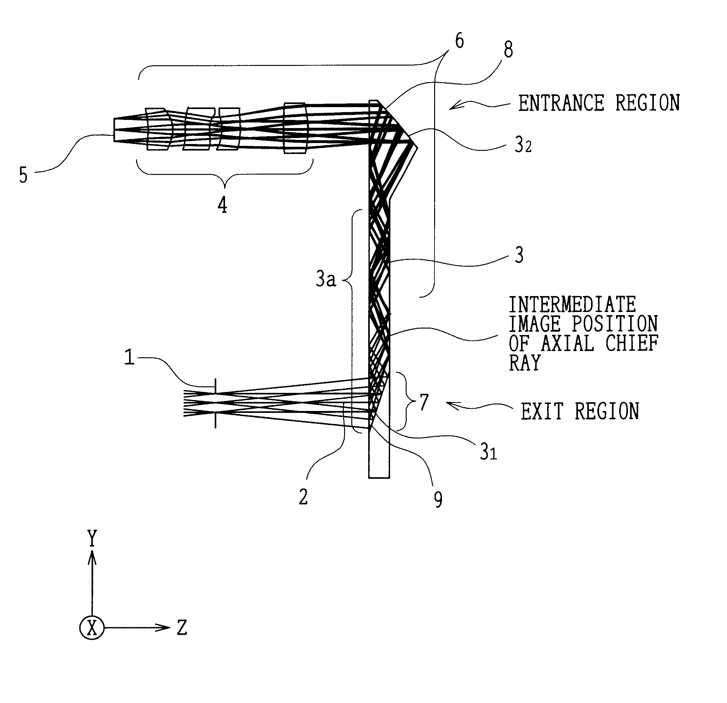
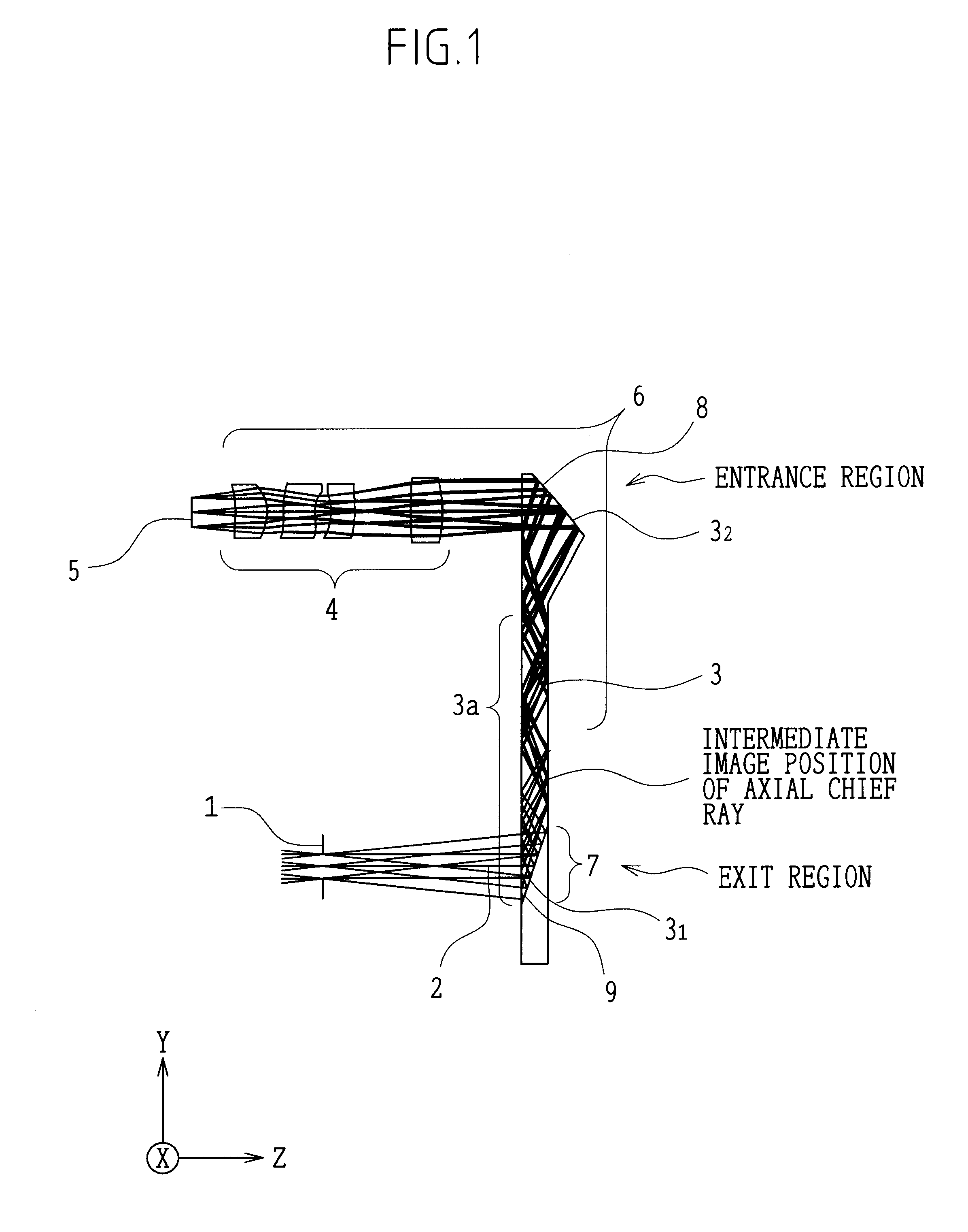
The observation optical system as shown in FIG. 1 includes a LCD 5 as the image display element which displays an image to be observed by an observer, a relay optical system 6 which relays image information formed on the LCD 5, and an eyepiece optical system 7 which introduces the image information relayed by the relay optical system 6 into the eye of the observer. Also, an exit pupil 1 is formed on the pupil surface so as to allow observation of the image displayed on the LCD 5.

The relay optical system has a plurality of lenses 4 and a first reflection-type HOE 8. The eyepiece optical system 7 has a second reflection-type HOE 9. The first reflection-type HOE 8 and the second reflection-type HOE 9 are formed on the predetermined base surfaces 3.sub.1, 3.sub.2, respectively, in the light-transmitting plate 3.

The light-transmitting plate 3 is filled with a transparent medium and is constructed and arranged to lead bundles of rays, which are reflected at least by the first reflection-...

second embodiment

In the observation optical system according to the second embodiment shown in FIG. 6, the base surface 3.sub.2 of the light-transmitting plate 3 is shaped as a plane surface. The remaining basic configuration is substantially the same as the first embodiment.

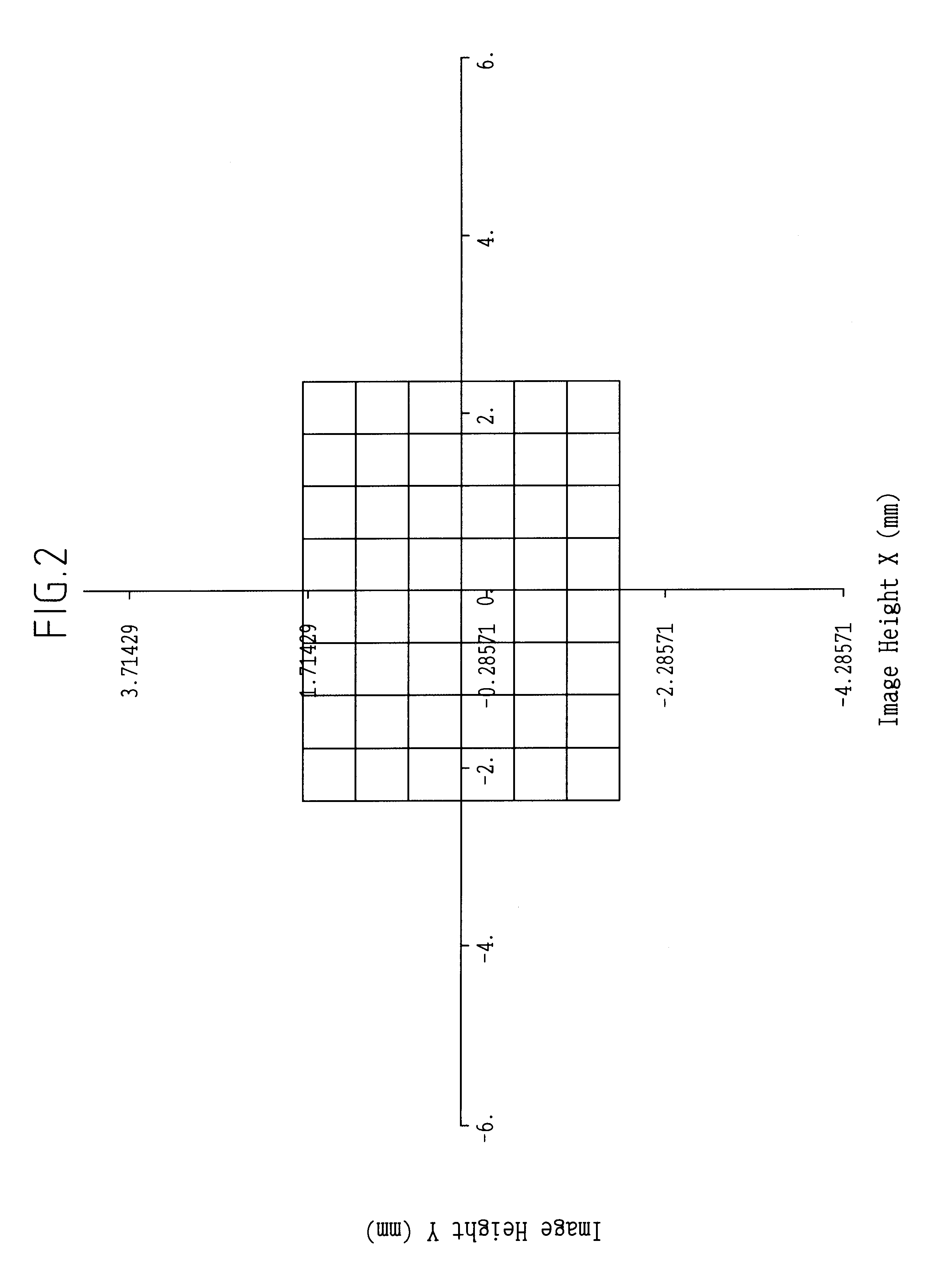
The numerical data of the second embodiment is shown below. Also, FIG. 7, which presents the image distortion of the second embodiment, is drawn in the same manner as FIG. 2. FIGS. 8A-8L, FIGS. 9A-9L and FIGS. 10A-10L, which show lateral aberrations in the wavelength regions of R, G and B, respectively, are drawn in the same manner as FIGS. 3A-3L, FIGS. 4A-4L and FIGS. 5A-5L.

Numerical Data 2

pupil diameter .phi.: 3 mm

horizontal full field angle: 12.00.degree.

vertical full field angle: 16.00.degree.

= 0.0 .gamma. = 0.0

Conditions:

third embodiment

In the optical system according to the third embodiment shown in FIG. 11, the plate surfaces of the light-transmitting plate 3 are shaped to have a curvature along the face of an observer. The configuration of the first embodiment or the second embodiment is applied to the remaining basic configuration.

Next, description is made of application examples where the observation optical system according to the present invention is used in a head-mount-type image display apparatus.

As shown in FIG. 12, a head-mount-type image display apparatus using the observation optical system according to the present invention is configured as a binocular image display apparatus having a pair of light-transmitting plates 3 for left and right eyes, a pair of cases 10 for left and right eyes, and a spectacle frame 11 which is held on the side heads of an observer. Each of the cases 10 holds therein an image display element 5 and a plurality of lenses as shown in FIG. 1 or FIG. 6. The light-transmitting pl...


PUM

PropertyMeasurementUnit
incident angleaaaaaaaaaa
center wavelengthsaaaaaaaaaa

Abstract

An observation optical system includes an image display element, a relay optical system having a plurality of lenses 4 and a first reflection-type volume hologram element (HOE), and an eyepiece optical system having a second reflection-type HOE. The observation optical system is arranged along the face to the side head of the observer. The first reflection-type HOE has a power and is configured to compensate for chromatic aberrations. The plurality of lenses is configured to compensate for decentered aberrations and chromatic aberrations. The second reflection-type HOE is a configured to exert power on bundles of rays and to compensate for chromatic aberrations. A light-transmitting plate is sandwiched between the first reflection-type HOE and the second refection-type HOE.

Description

1) Field of the InventionThe present invention relates to an observation optical system. To be specific, it relates to an observation optical system used in an image display apparatus that can be held on the head or face of an observer and that can be attached to a cellular phone or a portable intelligent terminal.2) Description of Related ArtIn recent years, development has been energetically made for image display apparatuses, specifically for those to be held on the head or face of individuals for entertaining them with a wide-screen image.Regarding the conventional observation optical systems applicable to such apparatuses, each of U.S. Pat. No. 4,613,200, International Application No. PCT / US99 / 26756 (Publication No. WO 00 / 28369), Japanese Patent Application Preliminary Publication (KOKAI) No. Hei 5-178120, Japanese Patent Application Preliminary Publication (KOKAI) No. Hei 5-077658 etc. proposes an image display optical system that achieves compensation for chromatic aberration...

Claims


Application Information

Patent Timeline
Patent Type & Authority Patents(United States)
IPC IPC(8): G02B27/01G02B5/32G02B27/00G02B5/18G02B13/18G02B17/08G02B25/00G02B27/02G02F1/13H04N5/64
CPCG02B5/32G02B27/0081G02B27/0172G02B2027/011G02B2027/0132G02B2027/0174G02B2027/0178
Inventor TAKEYAMA, TETSUHIDE
Owner OLYMPUS CORP
Why Eureka
Try Eureka