

Techniques, systems and machine readable programs for magnetic resonance
a magnetic resonance and machine-readable technology, applied in the field of methods for detecting and imaging molecules, can solve the problems of high cost and environmental risks, difficult detection or even impossible under clinically feasible conditions, and the patient is subject to a radioactive burden
- Summary
- Abstract
- Description
- Claims
- Application Information
AI Technical Summary
Benefits of technology
Problems solved by technology
Method used
Image

Examples
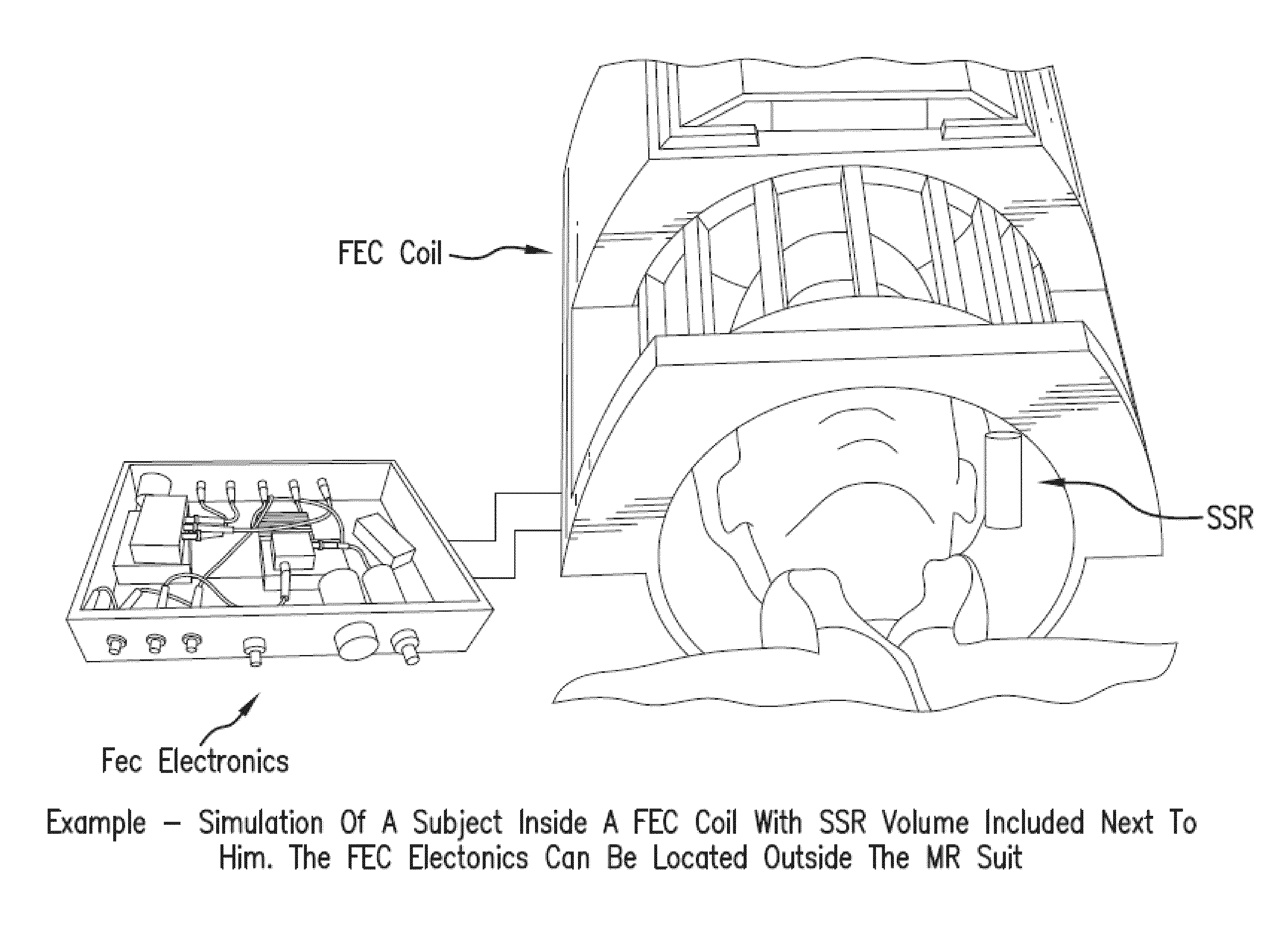
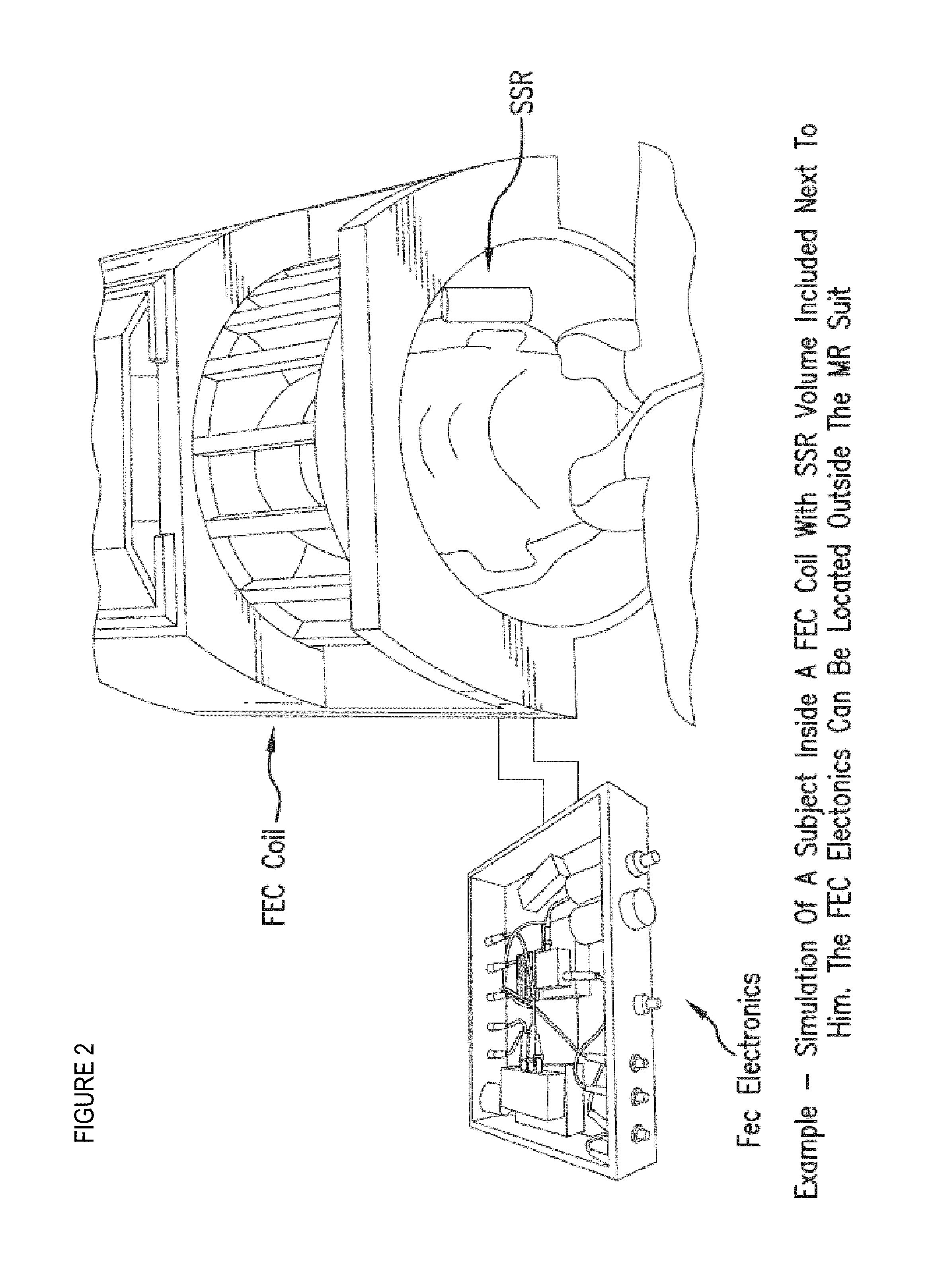
example
[0136]In one example, a commercially available head coil (e.g., FIG. 10C) (e.g., single channel) for operation on a 1.5T Siemens Avanto MRI scanner (FIG. 10A) can be used, and modified to be operated using a feedback circuit with a isolator block as set forth above with respect to FIG. 9, such as the illustrative embodiment depicted in FIG. 10B. A low power amplifier can be used initially (˜10 watts) to test the feedback circuit, to insure against positive feedback, and to obtain initial results.
[0137]Yet a further embodiment of an illustrative circuit is provided in FIG. 11. The illustrated circuit provides time interleaved feedback by separating the radiation damping (“RD”) transmit and receive in time. This approach has the benefit of avoiding positive feedback and thus allows larger gains to be applied. This in turn can allow for shorter RD time constants. A description of the circuit follows. The SPDT switch is used to change between the normal MR scanner operation and RD feedb...
PUM
 Abstract
Description
Claims
Application Information