
Aircraft with wings and movable propellers

a propeller and aircraft technology, applied in the field of flight vehicles, can solve the problems of failure and loss of helicopters, lack of vertical takeoff or landing capabilities of most airplanes, and inability to shorten the takeoff or landing time, etc., and achieve the effects of high lift, good performance and high altitude performan

Active Publication Date: 2015-11-17
SHAW DONALD ORVAL
View PDF42 Cites 130 Cited by
  • Summary
  • Abstract
  • Description
  • Claims
  • Application Information

AI Technical Summary

Benefits of technology

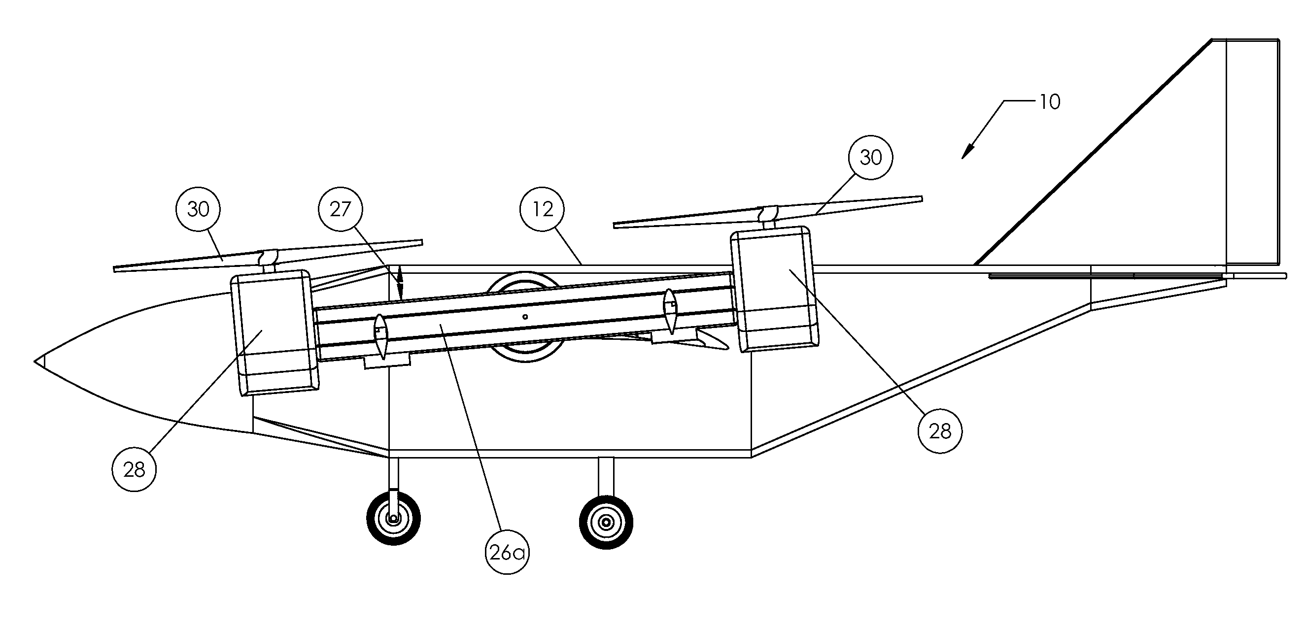
[0012]The connecting propeller support has sufficient length to position the propellers well clear of the wing in order to reduce or eliminate propeller thrust from striking the wing—regardless of which rotational position the connecting propeller support is rotated. In one embodiment of the invention, the connecting propeller support has a length which is slightly greater than the propeller diameter(s).
[0036]Navigation systems can include GPS systems and other modern navigation methods. An autopilot can be used, including many of the helicopter-type state of the art autopilots currently available, such as a Piccolo 2 series autopilot when interfaced with neural net computer software like the one that the Naval Research Laboratory has developed for their SPIDER Helicopter. In addition to other navigation systems, an obstacle avoidance system such as a scanning laser system may be employed to find obstacles in the air vehicle flight path. Difficult-to-spot obstacles such as power lines, etc. may be located using map data, etc. Other aircraft can be avoided through the use of transponder information, by receiving secure data by friendly aircraft as to where they are by GPS coordinates, etc.

Problems solved by technology

While airplanes have excellent lifting capacity and altitude capabilities, most airplanes lack vertical takeoff or landing (VTOL) or even short takeoff or landing (STOL) capabilities, and they typically require a large open space for takeoff and landing.
In many rugged landing sites, traditional airplanes are not suitable.
Helicopters are sometimes subject to accidents and failures, such as engine or rotor failures, which in some situations will lead to a failure and loss of the helicopter.
Additionally, many helicopters have difficulty operating at high altitudes.
Helicopters also tend to have slower flight speeds than do traditional aircraft.
A complication of many tilt-rotor designs is that the wing structure blocks a portion of the propeller or rotor thrust.
This interaction of propwash with the wing reduces the thrust provided for forward thrust and / or vertical / short lift-off / landing, and also can interfere with aircraft controls and stability.

Method used


Image

  • Aircraft with wings and movable propellers
  • Aircraft with wings and movable propellers
  • Aircraft with wings and movable propellers

Examples


Embodiment Construction

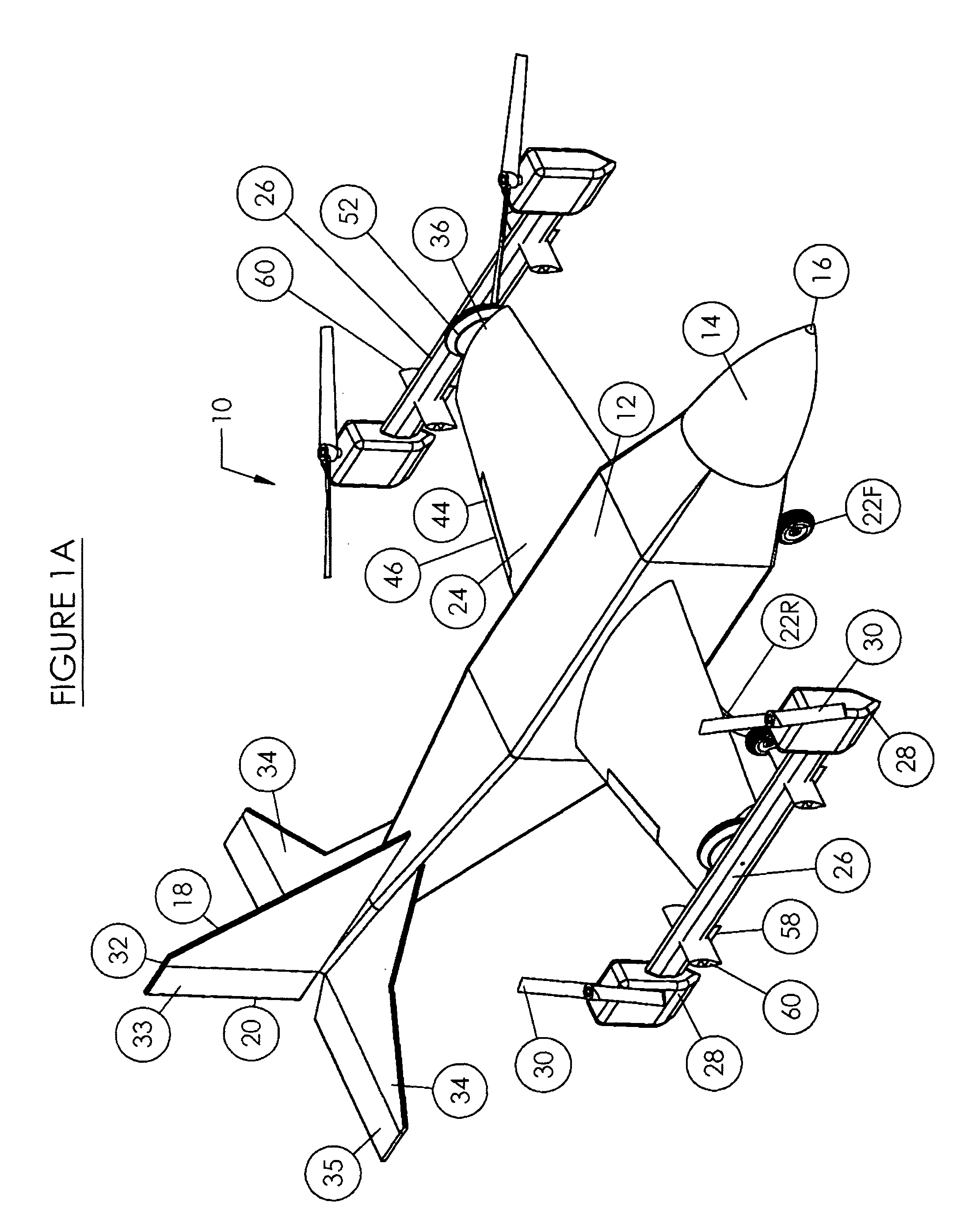
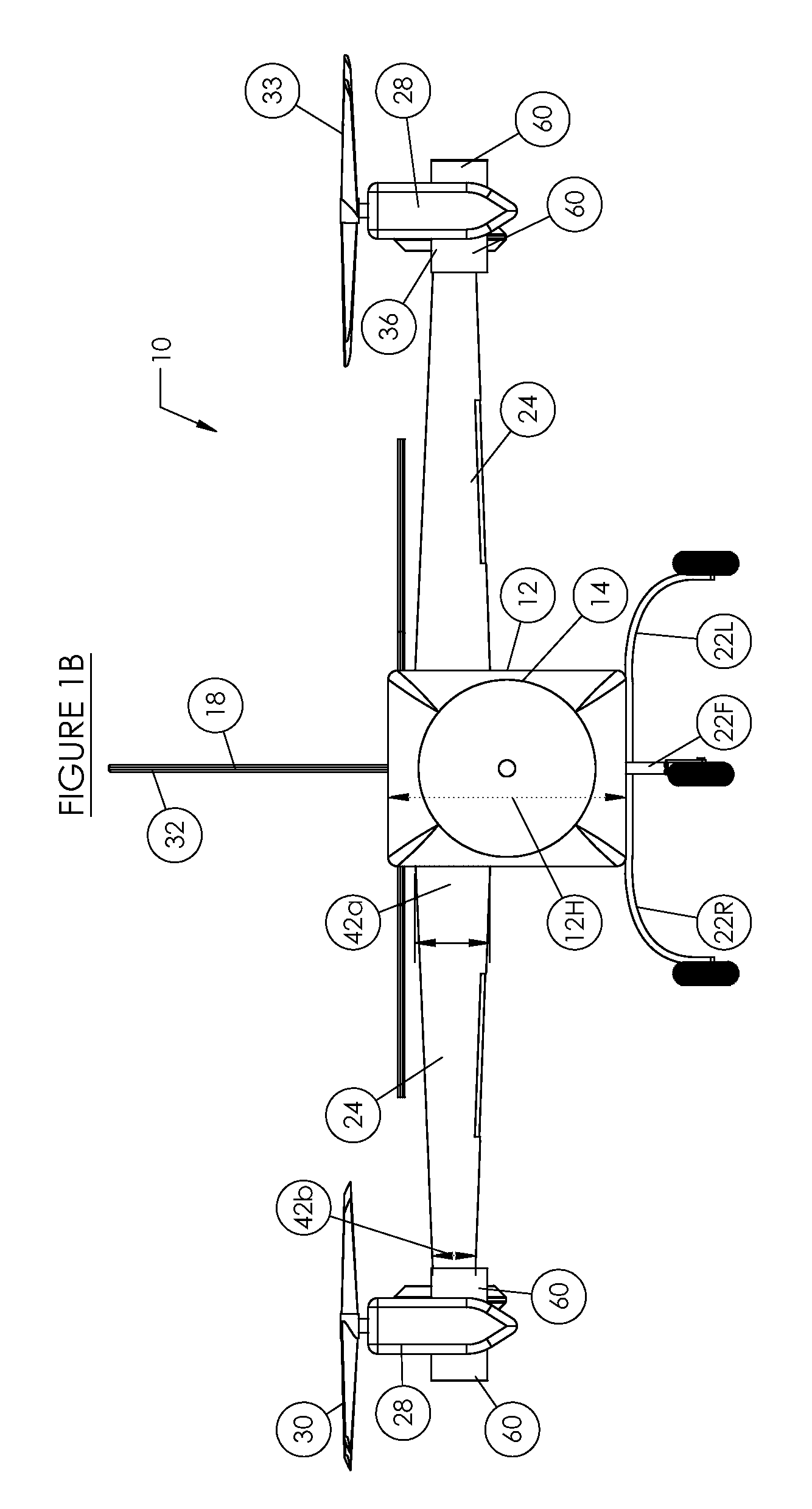
[0070]FIGS. 1A-1D depict an aircraft 10 according to the invention. The aircraft 10 includes a fuselage 12, nose 14 positioned at the aircraft front 16, tail assembly 18 positioned at the aircraft rear 20, landing gear (front 22F, left 22L, right 22R), wings 24, propeller supports 26, engines 28, and propellers 30.

[0071]The fuselage 12 can be of various sizes, with the specific size dependent on the particular application, including characteristics such as payload, range, speed, etc. In one embodiment of the invention, the fuselage has a length 12L (nose to tail), a width 12W, and a height 12H. Some or all of the landing gear 22F, 22L, 22R may retract into the fuselage 12.

[0072]The tail assembly 18 comprises a vertical stabilizer 32 and horizontal stabilizers 34. The vertical stabilizer may be configured to rotate left or right, and / or may include a vertical stabilizer flap 33. In the particular embodiment depicted, the horizontal stabilizers 34 are generally in line with the plane ...


PUM


Abstract

The invention is a flight vehicle, and methods of operation thereof, having wings and movable propeller assemblies which can be rotated to provide vertical and / or horizontal thrust. The propeller assemblies are configured to maximize available engine / propeller thrust and to prevent propwash from striking the wings of the aircraft.

Description

RELATED APPLICATIONS[0001]The present application claims priority from U.S. Provisional Application No. 61 / 390,611, filed on Oct. 6, 2010 and entitled “Aircraft with Wings and Movable Propellers,” the entire contents of which are expressly incorporated herein by reference. The present application is related to U.S. Provisional Application No. 60 / 901,809 filed on Feb. 16, 2007, to U.S. Utility application Ser. No. 12 / 070,669 filed on Feb. 19, 2008, and to U.S. Provisional Application No. 61 / 332,817, filed on May 10, 2010, the entire contents of each of which are hereby incorporated by reference.FIELD OF THE INVENTION[0002]The present invention relates to flight vehicles, and more particularly to flight vehicles configured to carry various payloads.BACKGROUND OF THE INVENTION[0003]Heavier-than-air flight vehicles have been known for that last 100 years or so, and include airplanes and helicopters. Such flight vehicles are used in many applications where speed is necessary to transport...

Claims


Application Information

Patent Timeline
Patent Type & Authority Patents(United States)
IPC IPC(8): B64C27/22B64C29/00B64C27/28
CPCB64C29/0033B64C27/28
Inventor SHAW, DONALD ORVAL
Owner SHAW DONALD ORVAL
Learn More