Check patentability & draft patents in minutes with Patsnap Eureka AI!

Eye bolt

a technology of eye bolts and threads, applied in the direction of hooks, load securing, transportation items, etc., can solve the problems of threaded bolts bending, bending, and even breaking, and achieve the effect of avoiding the disadvantages shown

Active Publication Date: 2015-11-17
PEWAG AUSTRIA
View PDF24 Cites 9 Cited by
  • Summary
  • Abstract
  • Description
  • Claims
  • Application Information

AI Technical Summary

Benefits of technology

Eliminates the need for separate tools, allows for alignment with the load direction, and enables secure operation in confined spaces by preventing unintentional separation or loss, while allowing for easy installation and removal without additional tools.

Problems solved by technology

Although these known eye bolts can be installed or removed without an additional tool, they have the disadvantage that they cannot be aligned in the direction of load and thus, when they are used, either they cannot be screwed in fully or may become unscrewed.
With such eye bolts designed as one piece, there is always the danger that the threaded stem will be overloaded or loosened by a torque acting on the lifting eye, which can result in the threaded bolt bending, or even breaking.
However, when they are installed or removed, it is necessary to use an additional tool (usually an Allen key) which then has to be stored again separately after installation or removal, wherein there is the danger that this key will be lost or mislaid.
However, this also requires the use of its own tool to turn the screw during installation or removal.
However, the tools described there protrude significantly onto the outside of the lifting eye both when engaged with the supporting bolt and when not engaged with the latter, which is why there is the danger, when used in a confined space, that the outwardly projecting part of the tool catches on an item located in the confined space when the eye is rotated, and then a further rotation of the lifting eye to screw in the supporting bolt may possibly be blocked.
However, this also entails the danger that, due to the elasticity of the material, the tool and the lifting eye can unintentionally become separated as a result of an external effect on the tool.

Method used


Image

  • Eye bolt
  • Eye bolt
  • Eye bolt

Examples


Embodiment Construction

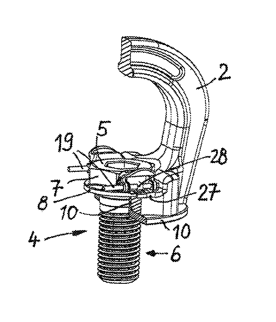
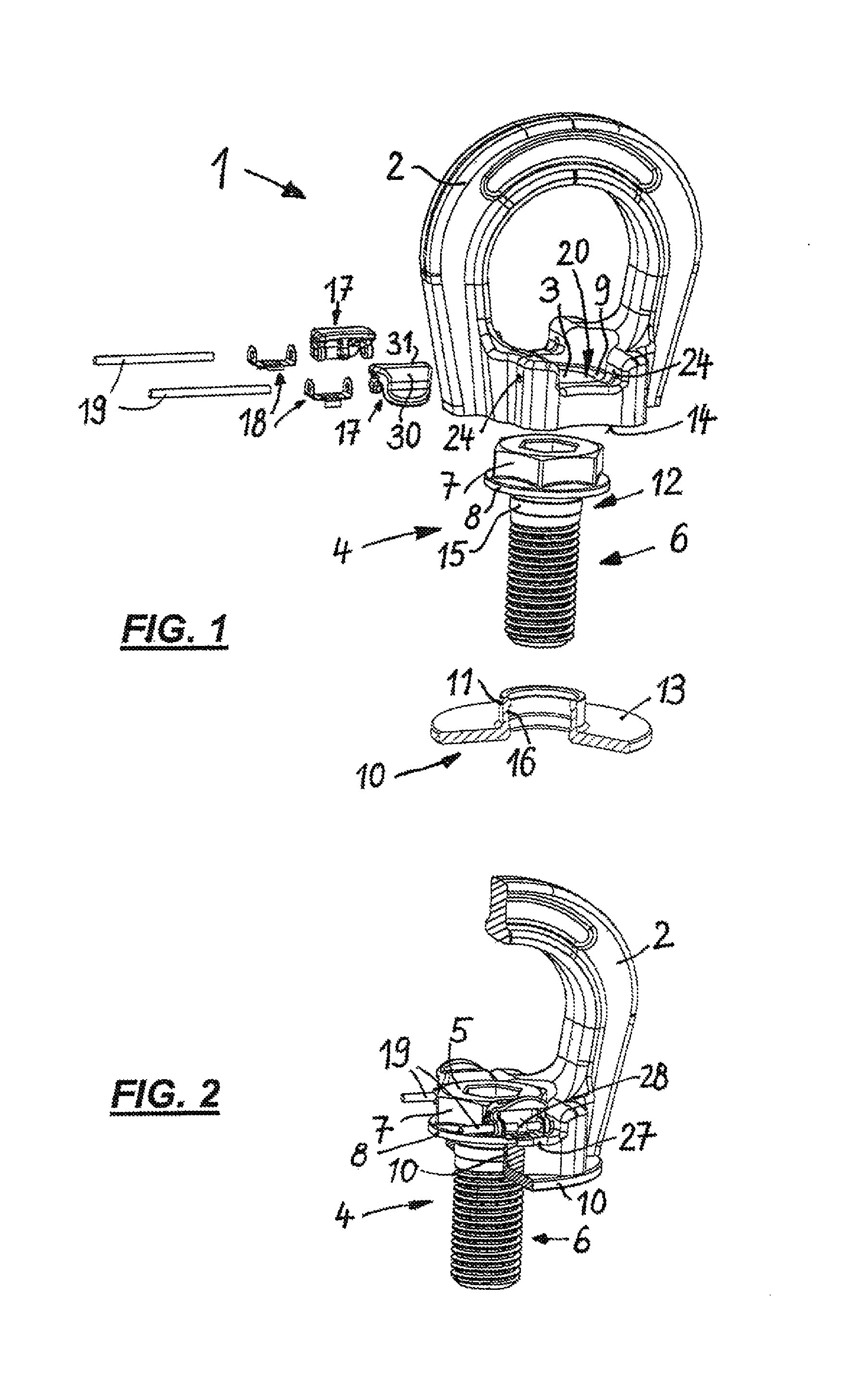
[0029]In the figures, a particularly preferred embodiment of an eye bolt 1 is shown which, as can best be seen from the perspective exploded representation of FIG. 1, comprises a lifting eye 2 which is provided in its lower section with an insertion opening 3 for insertion of a supporting bolt 4. This has a bolt head 5 as well as a threaded shaft 6 with which the eye bolt 1 can be screwed onto an item for accommodating it.

[0030]The bolt head 5 of the supporting bolt 4 is provided with a hexagon head 7 which sits on a circumferential ring band 8.

[0031]When the eye bolt 1 is assembled, the supporting bolt 4 rests with the underside of the ring band 8 on a flat bearing surface 9, formed on the lifting eye 2 and running around the insertion opening 3, and is supported from below on the latter.

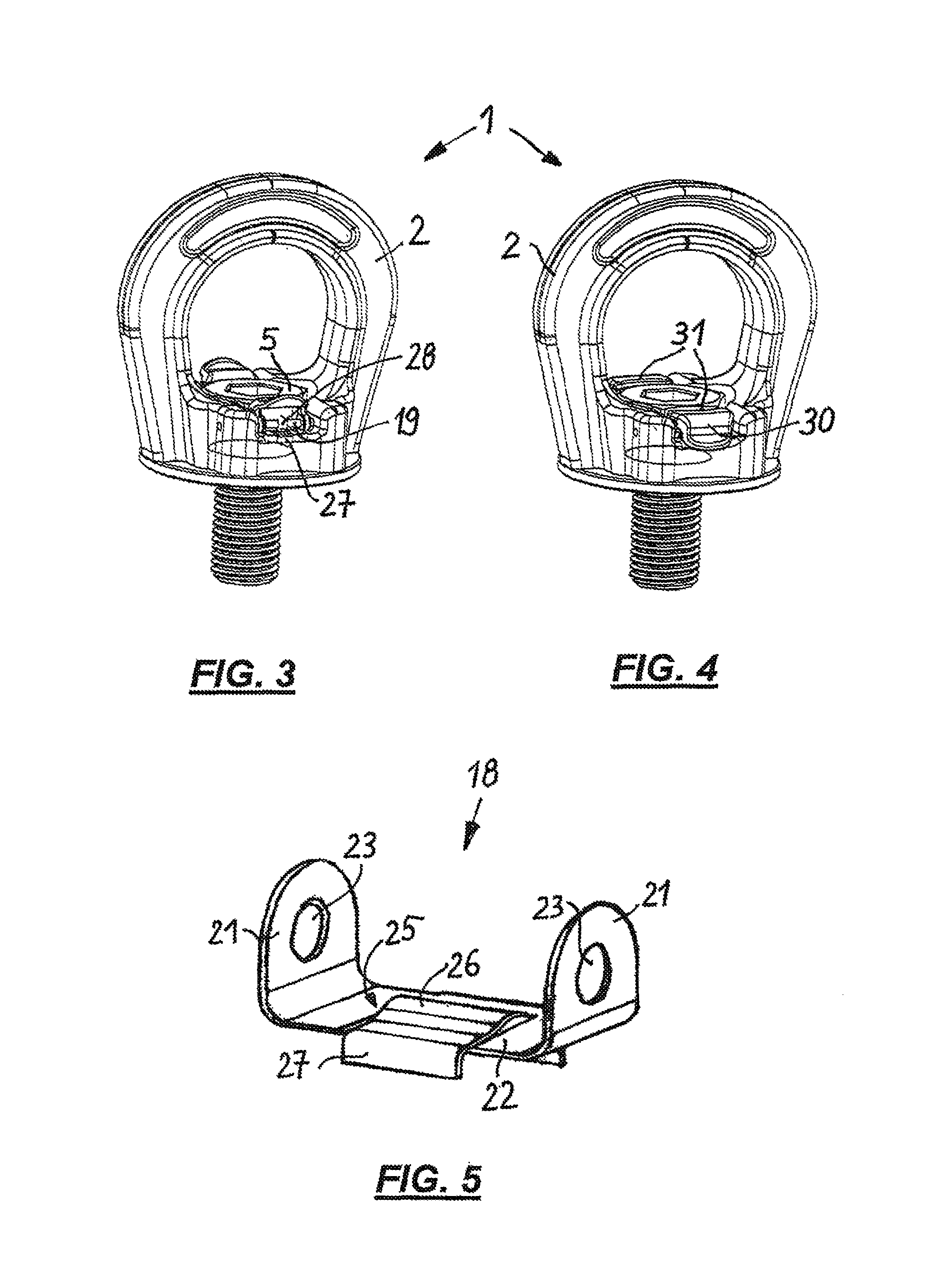
[0032]As FIG. 2 shows, in the perspective representation of which however the lifting eye 2 is represented cut in a vertical center plane (in which the center axis of the supporting bolt 4 also lie...


PUM


Abstract

An eye bolt, comprising a lifting eye and a supporting bolt, wherein the supporting bolt sits, rotatable, in an insertion opening of the lifting eye and comprises, a threaded shaft and a bolt head. The supporting bolt protrudes radially from the lifting eye and is supported by an underside of the lifting eye, on a bearing surface formed on the lifting eye and running around the insertion opening. The eye bolt further comprises at least one locking member which can be brought into engagement with the bolt head and by means of which, in a locking position of same, the bolt head can be rotationally blocked vis-à-vis the lifting eye. The at least one locking member is further attached to the lifting eye radially next to the bolt head and is secured there, wherein the at least one locking member can be brought into a starting position, in which it is not engaged with the bolt head, and also into the locking position rotationally blocking the supporting bolt relative to the lifting eye.

Description

PRIORITY CLAIM[0001]The present application is a National Phase entry of PCT Application No. PCT / EP2010 / 007326, filed Dec. 2, 2010, the disclosure of which is hereby incorporated by reference herein in its entirety.FIELD OF THE INVENTION[0002]The invention relates to an eye bolt with a lifting eye and a supporting bolt which sits, rotatable, in an insertion opening of the lifting eye, is provided with a threaded shaft and has a bolt head, protruding radially from the latter, which is supported, by its underside, on a bearing surface formed on the lifting eye and running around the insertion opening, and with at least one locking member which can be brought into engagement with the bolt head and by means of which, in a locking position of same, the bolt head can be rotationally blocked vis-à-vis the lifting eye.BACKGROUND OF THE INVENTION[0003]Eye bolts in which the supporting bolt in the form of a threaded stem is secured in one piece to the lifting eye and, by rotating them, can be...

Claims


Application Information

Patent Timeline
Patent Type & Authority Patents(United States)
IPC IPC(8): F16B45/00B60P7/08
CPCF16B45/00B60P7/0807Y10T403/32213B66C1/66F16B35/00F16B45/002
Inventor IVANIC, RANKOPENGG, AGYD
Owner PEWAG AUSTRIA
Features
  • R&D
  • Intellectual Property
  • Life Sciences
  • Materials
  • Tech Scout
  • Unparalleled Data Quality
  • Higher Quality Content
  • 60% Fewer Hallucinations
Learn More