Whole fiber switched p-cycles

a fiber optic network and cycle technology, applied in the field of whole fiber optic switching, can solve the problems of bringing more complexity and computational problems in the conventional p-cycle network design problem, affecting the performance of the network,

Inactive Publication Date: 2015-12-29
TR TECH
View PDF5 Cites 0 Cited by
  • Summary
  • Abstract
  • Description
  • Claims
  • Application Information

AI Technical Summary

Problems solved by technology

But wavelength switching may also involve higher costs mainly due to operations in the electronic domain.
Furthermore, obtaining a CapEx cost-effective design using span-protecting p-cycles required to substitute wavelength for glass switched p-cycles, with the cost of ports on the hypothetical fiber switch estimated to be 10% of the cost of wavelength selective ports on a traditional OXC.
From another perspective, wavelength assignment and wavelength continuity constraints required in the restored state for fully transparent p-cycle network architectures certainly bring more complexity and computational issues in the conventional p-cycle network design problem.
But the study was limited to the usage of Hamiltonian structures only.
But despite so many advantages, the practicability of p-cycles vis-à-vis that of path-protecting pre-cross-connected schemes has remained questionable from the capital expenditure (CapEx) cost perspective because of wavelength switching operations.
Where wavelength conversion is allowed, either at p-cycle entry nodes or at every node crossed en route, high equipment costs are incurred because of optic-electronic-optical (o-e-o) conversion from one span to the next, or from the working path to the protection cycle and vice versa.
And yet, while nodes and single DWDM channels may fail, a pre-dominant source of unavailability is physical damage to optical cables.
As will be shown in the detailed description, fully transparent p-cycles also bring computational issues and much more complexity in the design because of wavelength assignment and wavelength continuity constraints.
Several reasons are probably that in the past, glass-switching fabrics used to be very slow in practice (1 s or more), bulky, expensive and limited in size to 16×16 or more typically 2×48 matrices.
For on-cycle span failures however, one of those sides is considered unusable; this is in recognition that a p-cycle cannot offer more than one restoration route for on-cycle failure events.

Method used


Image

  • Whole fiber switched <i>p</i>-cycles
  • Whole fiber switched <i>p</i>-cycles
  • Whole fiber switched <i>p</i>-cycles

Examples


Embodiment Construction

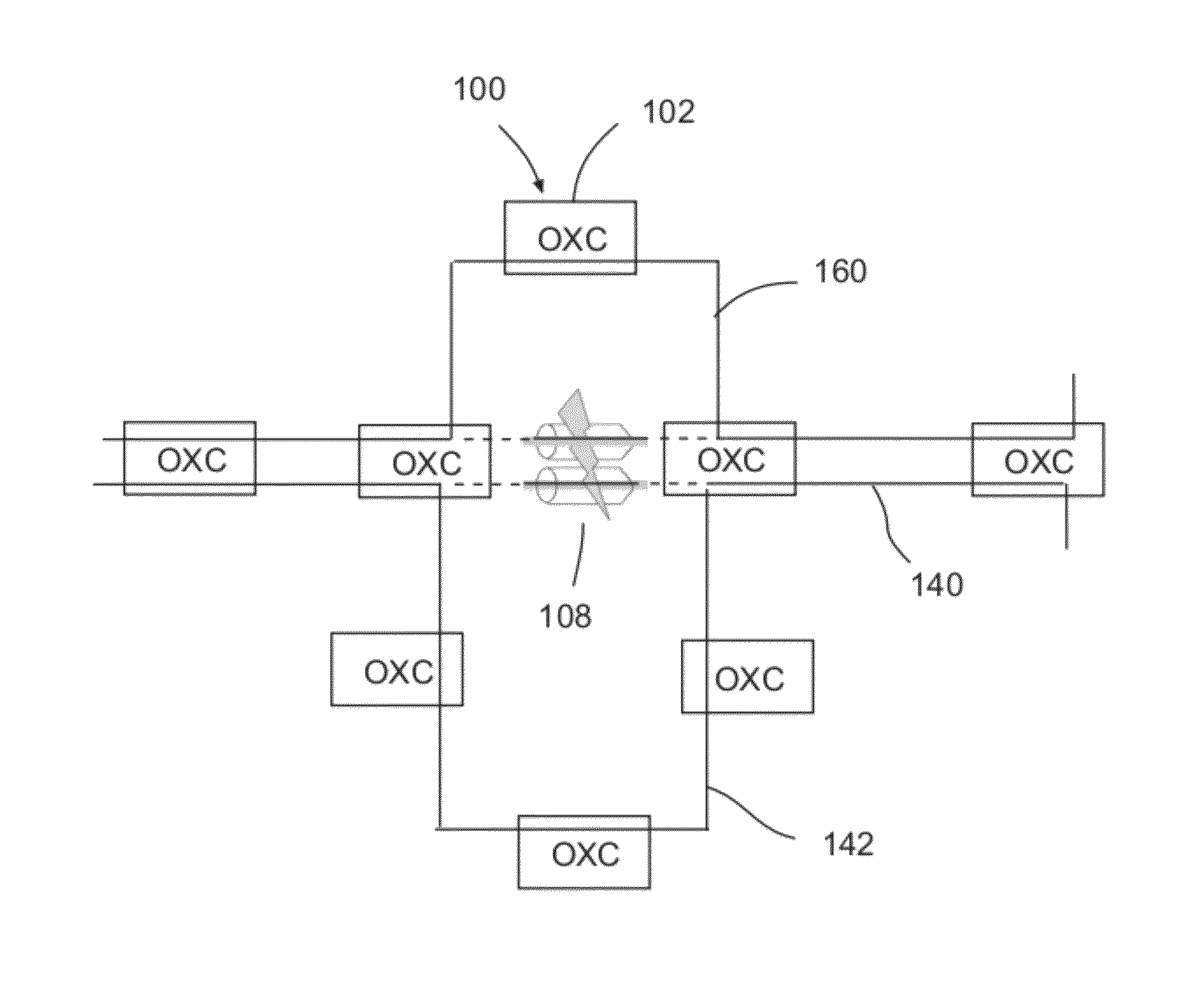
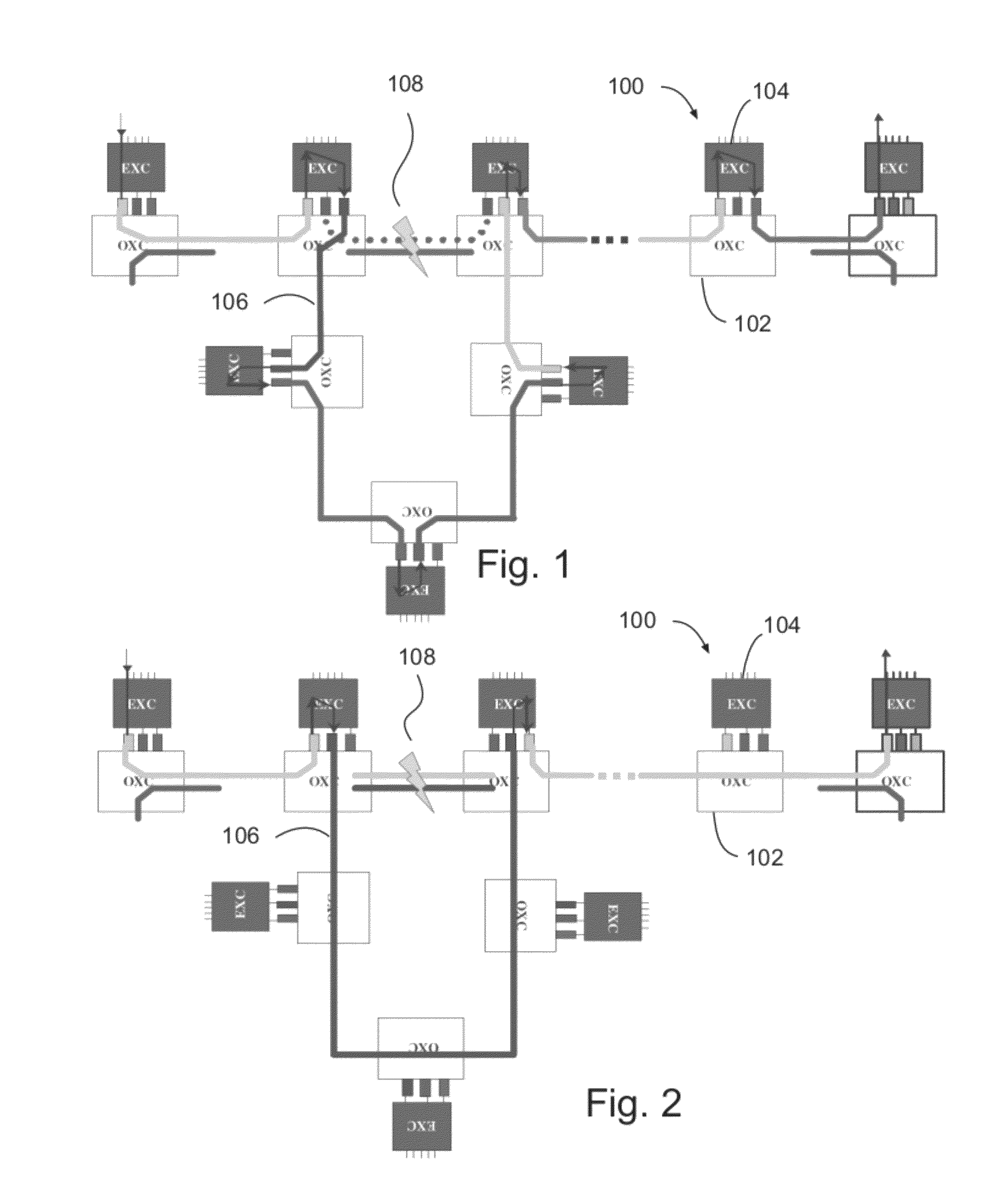
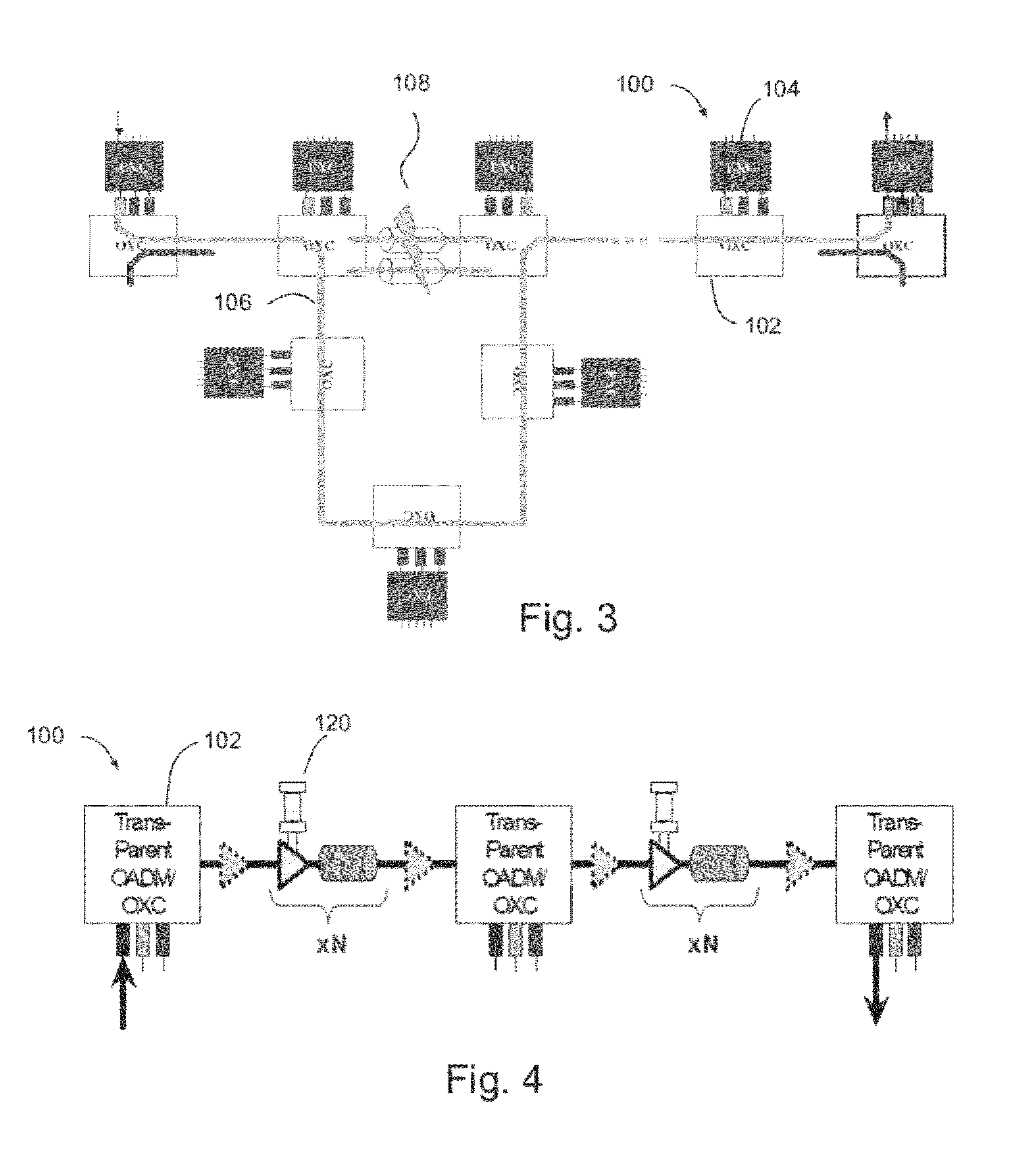
[0033]FIGS. 1-3 respectively show opaque, hybrid and fully transparent p-cycle designs. For each configuration type, the first lines in FIGS. 1-3 illustrate pre-failure state paths; while the bottom lines plus the second and third nodes in the first lines, and their connecting links comprise p-cycles. In each of FIGS. 1-3, nodes 100 comprise optical cross-connect switches 102 and electrical cross-connect switches 104. Links 106 between nodes may correspond to channels for particular wavelengths in the opaque or hybrid cases or entire fibers in the transparent case. Span failure 108 is typically assumed to affect all channels and fibers of the span.

[0034]The opaque configuration case (FIG. 1) implies wavelength discontinuities and thus, o-e-o conversion at every node across working paths and along p-cycles. This means every working path and p-cycle leaves and re-enters the optical domain to access the next span on which it probably rides onto a different wavelength.

[0035]In the hybri...


PUM


Abstract

A communication network in which p-cycles are used to rapidly, simply and efficiently provide for the direct replacement of failed fiber sections with whole replacement fibers. As long as the loss budgets are adequate, entire DWDM wavebands can be restored with no switching or manipulation of individual lightpaths. Following a substitution transient, the DWDM layer would never know the break happened. In environments where fiber switching devices are low cost, and ducts are full of dark fiber, this could provide a very low cost alternative to protect an entire DWDM transport layer (or working capacity envelope) against the single largest cause of outage.

Description

BACKGROUND[0001]p-Cycle survivable networks were introduced in the late 1990s, with the aim of bringing the simplicity and rapidity of survivable rings in the much more flexible and efficient full mesh-based context. There has been an increased interest in p-cycles over the last decade. But related prior research on p-cycles mainly assumes an optical switching based on the wavelength level of granularity. p-Cycles' configuration on a per-wavelength basis is generally more than attractive from the perspective of flexibility in the routing of working paths and freedom in the selection of protecting structures.[0002]But wavelength switching may also involve higher costs mainly due to operations in the electronic domain. This is often the case in opaque transport networks where wavelength discontinuities require optic-electronic-optic (o-e-o) conversion capabilities at every node across working paths and p-cycles. Wavelength conversion is also partially required, at least at the entry p...

Claims


Application Information

Patent Timeline
Patent Type & Authority Patents(United States)
IPC IPC(8): G02B6/26H04J14/02H04J3/14
CPCH04J14/0268H04J14/0284H04J14/0213H04J14/0212
Inventor GROVER, WAYNE D.
Owner TR TECH
Why Eureka
Try Eureka