Liquid storage container and cover therefor

a technology which is applied in the field of liquid storage container and cover, can solve the problems of inability to print, waste, and ink leakage to the inside of the cover from the liquid outflow, and achieve the effect of curbing the waste of ink in the cartridg

Active Publication Date: 2016-02-02
SEIKO EPSON CORP
View PDF10 Cites 0 Cited by
  • Summary
  • Abstract
  • Description
  • Claims
  • Application Information

AI Technical Summary

Benefits of technology

[0006]The cartridge of Patent Document 1 has a problem in that ink that has leaked out to inside the cover from the liquid outflow part in the state where the cover has been mounted onto the cartridge cannot be used for printing and goes to waste. There has therefore been a desire for a feature making it possible to curb the waste of ink in the cartridge.

Problems solved by technology

The cartridge of Patent Document 1 has a problem in that ink that has leaked out to inside the cover from the liquid outflow part in the state where the cover has been mounted onto the cartridge cannot be used for printing and goes to waste.
The problems described are not limited to cartridges for storing ink, but rather are common also to liquid storage containers for storing other liquids.

Method used


Image

  • Liquid storage container and cover therefor
  • Liquid storage container and cover therefor
  • Liquid storage container and cover therefor

Examples


first embodiment

A. First Embodiment

[0040]A-1. Overall Configuration of the Liquid Jet System

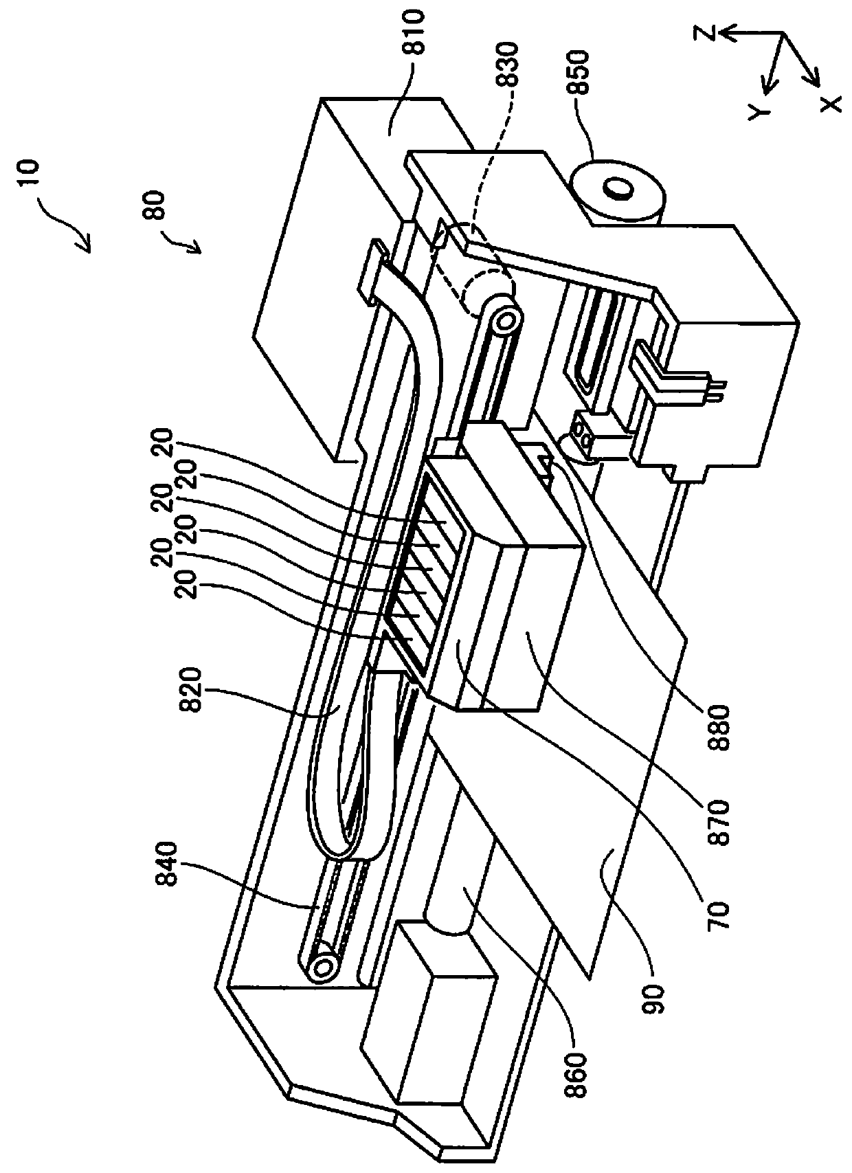
[0041]FIG. 1 is a perspective view illustrating the configuration of a liquid jet system 10. FIG. 1 illustrates X-, Y-, and Z-axes, which are orthogonal to one another. The X-, Y-, and Z-axes in FIG. 1 correspond to the X-, Y, and Z-axes in the other drawings. In the present embodiment, the Z-axis in the X-, Y-, and Z-axes is an axis that runs along the force of gravity in the state of use of the liquid jet system 10. The +Z-axis direction is the upward direction opposite to the direction of the force of gravity, and the −Z-axis direction is the direction of the force of gravity, i.e., the downward direction. The “state of use of the liquid jet system 10” refers to a state where the liquid jet system 10 is installed on a horizontal plane; in the present embodiment, the XY-plane is the horizontal plane.

[0042]The liquid jet system 10 is provided with cartridges 20, which are liquid storage containers, and with...

second embodiment

B. Second Embodiment

[0097]FIG. 13 is a descriptive view where a cover 52 in a second embodiment is viewed from above. FIG. 14 is an enlarged cross-sectional view where the cover 52 in the second embodiment is transected. FIG. 14 depicts the cover 52 as being transected along with the cartridge 20 along the arrow F14-F14 in FIG. 13. The liquid jet system 10 of the second embodiment is similar to that of the first embodiment, except in that the cover 52, which is different from that of the first embodiment, is mounted onto the cartridge 20.

[0098]The cover 52 of the second embodiment is similar to that of the first embodiment, except in that grooves 585 extending from the communication port 280 side to the inclined part 582 side (in other words, towards the inclined part 582) are formed on the upper part 584 of the contact part 580. In the present embodiment, a plurality of grooves 585 are formed on the upper part 584. In another embodiment, there can be a single groove 585 formed on t...

third embodiment

C. Third Embodiment

[0100]FIG. 15 is an enlarged cross-sectional view where a cover 53 in a third embodiment is transected. FIG. 15 depicts the cover 53 as transected along with the cartridge 20 in a positional relationship similar to that of FIG. 12. The liquid jet system 10 of the third embodiment is similar to that of the first embodiment, except in that a cover 53 which is different from that of the first embodiment is mounted onto the cartridge 20. The cover 53 of the third embodiment is similar to that of the first embodiment, except in that the upper part 584 of the contact part 580 contacts with the welded part 276 of the cartridge 20 in the state where the cover 53 is mounted onto the cartridge 20.

[0101]According to the third embodiment, similarly with respect to the first embodiment, the inclined part 582 of the contact part 580 makes it possible to curb the extent to which the ink that has leaked out to the cover 52 from the liquid outflow part 274 goes to waste. Further, ...


PUM


Abstract

A liquid storage container includes a liquid storage part, a liquid supply part, a liquid outflow part, and a cover. The liquid storage part stores a liquid. The liquid supply part has a liquid supply port defining an opening by which the liquid is supplied to a liquid jet apparatus from the liquid storage part. The liquid outflow part is made of a porous material. The liquid outflow part is disposed inside of the liquid supply port and allows the liquid to flow out to the liquid jet apparatus from the liquid storage part. The cover includes a sealing part contacting with the liquid supply part and sealing off the liquid supply port, the sealing part and the liquid outflow part defining a space therebetween, and a contact part made of a non-porous material, the contact part contacting with a part of the liquid outflow part.

Description

CROSS-REFERENCE TO RELATED APPLICATIONS[0001]This application claims priority to Japanese Patent Application No. 2013-174070 filed on Aug. 26, 2013. The entire disclosure of Japanese Patent Application No. 2013-174070 is hereby incorporated herein by reference.BACKGROUND[0002]1. Technical Field[0003]The present invention relates to a liquid storage container and a cover therefor.[0004]2. Related Art[0005]One known liquid storage container is a cartridge for storing ink (a print material) for supply to a printer (print apparatus). Such a cartridge is provided with a liquid supply part and a liquid outflow part. The liquid supply part of the cartridge is provided with a liquid supply port, which is an opening configured so that the ink can be supplied to the printer. The liquid outflow part of the cartridge is formed of a filter, which is a porous medium made of a porous material, and is provided to the inside of the liquid supply port and causes the ink to flow out to the printer by ...

Claims


Application Information

Patent Timeline
Patent Type & Authority Patents(United States)
IPC IPC(8): B41J2/175
CPCB41J2/17536B41J2/1753B41J2/17513B41J2/17553B41J2/17556
Inventor MIZUTANI, TADAHIROTOBA, KOICHIKOBAYASHI, ATSUSHI
Owner SEIKO EPSON CORP
Why Eureka
Try Eureka