Ink supplying container and image forming apparatus

a technology of image forming apparatus and supplying container, which is applied in printing and other directions, can solve the problems of large reduction of pressure required for suctioning ink, inability to use suction recovery method in inkjet, and difficulty in sealing the surface of the nozzle with the cap, etc., and achieves simple structure, stably restrain flexible members from expanding, and waste of ink

Inactive Publication Date: 2007-03-15
RICOH KK
View PDF5 Cites 14 Cited by
  • Summary
  • Abstract
  • Description
  • Claims
  • Application Information

AI Technical Summary

Benefits of technology

[0032] According to an embodiment of the present invention, in an ink supplying container of the present invention, when the internal pressure of an ink container is made a positive pressure to execute cleaning and recovering operations of nozzles of a recording head, a flexible member of the ink container is restrained from expanding; and when the internal pressure of the ink container is made a negative pressure to execute printing a letter and / or an image on a recording medium, the flexible member of the ink container is not restrained from expanding. Further, the volume of the ink container at the time when the internal pressure of the ink container is made the positive pressure is maintained at almost the same volume as that of the ink container at the time when the internal pressure of the ink container is made the negative pressure optimal for printing. Therefore, by only discharging a small amount of ink from the ink container when the cleaning and recovering operations of the nozzles of the recording head are executed by pressure applying recovering method, the internal pressure of the ink container can be the negative pressure optimal for printing. With this, waste ink at the cleaning and recovering operations of the nozzles of the recording head can be reduced, where the negative pressure is lower than atmospheric pressure and the positive pressure is higher than the atmospheric pressure.
[0033] In addition, in order to restrain the flexible member of the ink container from expanding, a stopping unit is used. The stopping unit has a shape conforming to the shape of the one side of the flexible member at one end at the time when the internal pressure of the ink container is made the negative pressure. When the moving position of the stopping unit is controlled by a moving unit, the flexible member can be stably restrained from expanding.
[0034] In addition, when moving position of the stopping unit is variable, the moving position of the stopping unit can be adjusted corresponding to a change of the position of the flexible member caused by a change of environment such as temperature. Therefore, even if the environment is changed, the volume of the ink container at the time of the positive pressure can be maintained at almost the same volume as that at the time of a negative pressure optimal for printing.
[0035] In addition, pressure chamber can be disposed. The pressure chamber contacts the flexible member of the ink container and makes the internal pressure of the pressure chamber the atmospheric pressure when the internal pressure of the ink container is made the negative pressure and applies pressure to the inside of the pressure chamber when the internal pressure of the ink container is made the positive pressure. When the pressure chamber is used, the flexible member of the ink container can be restrained from expanding by a simple structure. In addition, when pressure is applied to inside the pressure chamber, if the pressure is applied so that the internal pressure of the pressure chamber is made almost the same pressure as that at the time when the internal pressure of the ink container is made the positive pressure, a breakdown of the recording head can be prevented by decreasing the influence of a rapid increase of the internal pressure of the ink container.
[0036] In addition, the ink supplying container includes an ink volume maintaining unit. The ink volume maintaining unit maintains the volume of the ink in the ink container including an auxiliary tank connected to the ink container in a predetermined amount when the internal pressure of the ink container is made the negative pressure and when the internal pressure of the ink container is made the positive pressure. Therefore, by only discharging a small amount of ink from the ink container when the cleaning and recovering operations of the nozzles of the recording head are executed by the pressure applying recovering method, the internal pressure of the ink container can be the negative pressure optimal for printing. With this, waste ink at the cleaning and recovering operations of the nozzles of the recording head can be reduced.
[0037] In addition, in an image forming apparatus using the ink supplying container of the present invention, waste ink at the cleaning and recovering operations of the nozzles of the recording head can be largely reduced and the ink can be effectively utilized by reducing the consuming amount of the ink.

Problems solved by technology

In the suction recovering method, when the size of the recording head is large, a large cap is needed to cover the recording head; therefore, it is difficult to seal the surface of the nozzles with the cap.
In addition, when the size of the recording head is large, a large reduction of the pressure is required for suctioning the ink.
Therefore, it is not suitable that the suction recovering method be used in an inkjet recording apparatus which has a long-length recording head.
On the other hand, in the pressure applying recovering method, when the size of the recording head is large, a moisture retaining property is required for the cap which covers the surface of the nozzles of the recording head; however, excessive sealing performance is not required; therefore, the structure is simple.
Therefore, every time at the recovering operations, the amount of the waste ink becomes large.
Especially, in an inkjet recording apparatus using a long-length recording head, the amount of the waste ink becomes remarkably large, and the ink cannot be effectively used.

Method used


Image

  • Ink supplying container and image forming apparatus
  • Ink supplying container and image forming apparatus
  • Ink supplying container and image forming apparatus

Examples


first embodiment

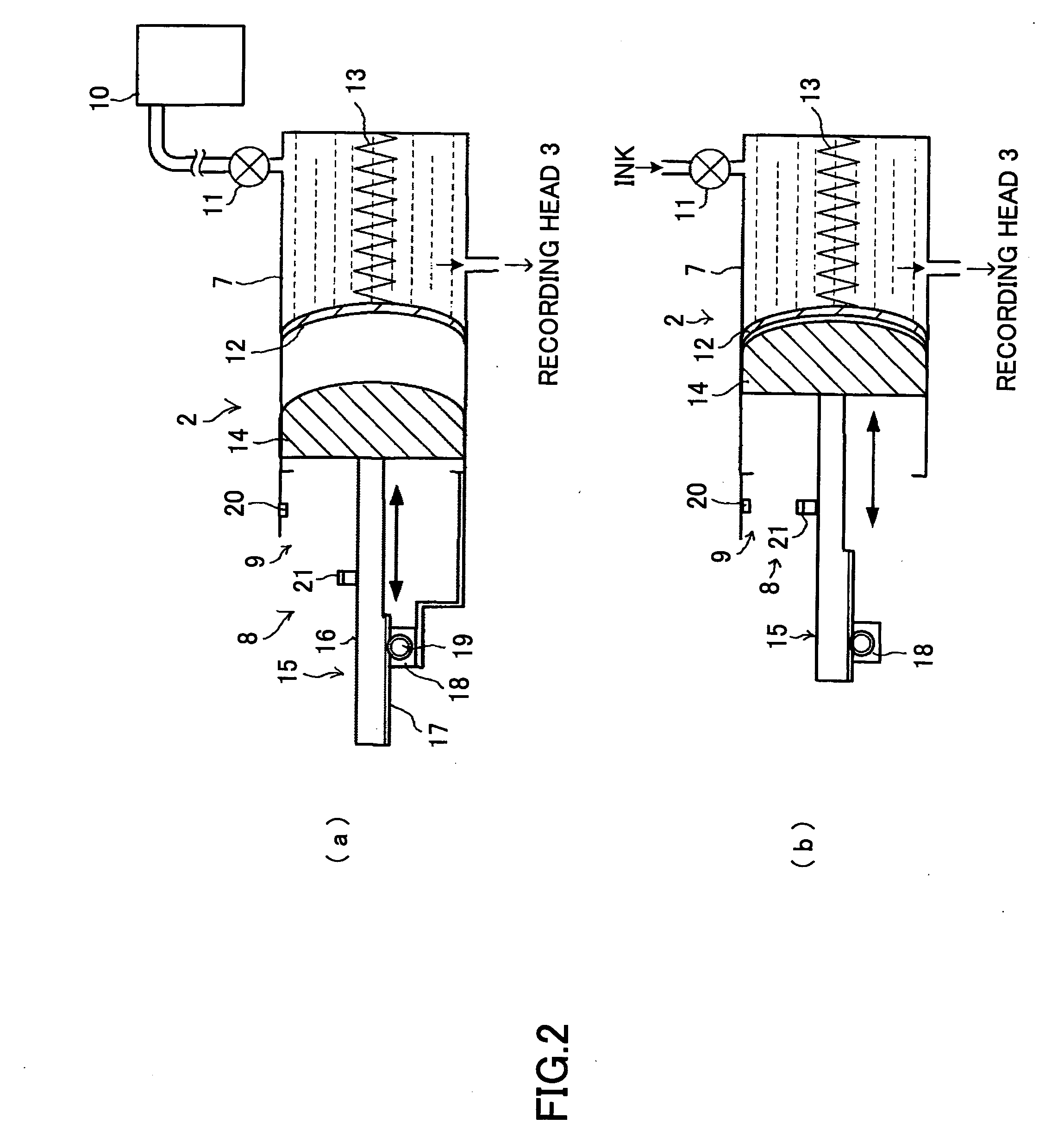
[0055]FIG. 2 is a schematic diagram of the sub tank 2 according to the present invention. In FIG. 2, (a) shows a printing state in which the sub tank 2 has a negative pressure for recording a letter and / or an image, and (b) shows a state in which the sub tank 2 has a positive pressure for recovering operations of the nozzles of the recording head 3. As shown in FIG. 2, the sub tank 2 includes an ink container 7, a volume control unit 8, and a position sensor 9. The ink container 7 is connected to a large capacity ink tank 10 from which ink is supplied to the ink container 7 via an ink supplying tube and a valve 11. The ink container 7 stores the ink supplied from the ink tank 10 and supplies the stored ink to the recording head 3. A flexible member 12 made of, for example, a resin film, is disposed at the side opposite to the connection section to the ink tank 10 of the ink container 7, and a compression spring 13 for pressing the flexible member 12 is disposed in the ink container ...

third embodiment

[0073]FIG. 8 is a schematic diagram of a sub tank 2b according to the present invention. In FIG. 8, (a) shows the sub tank 2b in a printing state and (b) shows a state in which the sub tank 2b is in recovering operations of the nozzles of the recording head 3. In FIG. 8, the volume control unit 8 is an ink volume maintaining unit.

[0074] As shown in FIG. 8, the volume control unit 8 in the sub tank 2b includes an auxiliary tank 38, a piston 39 disposed in the auxiliary tank 38, and the moving mechanism 15 which moves the piston 39. As shown in FIG. 8(a), when the sub tank 2b is in the printing state, the internal pressure of the ink container 7 is made a negative pressure optimal for printing by running a part of ink in the ink container 7 into the auxiliary tank 38 by the movement of the piston 39. As shown in FIG. 8(b), when the sub tank 2c is in the recovering operations of the nozzles of the recording head 3, before or when ink is supplied into the ink container 7 by pressure by ...

fourth embodiment

[0076]FIG. 9 is a schematic diagram of a sub tank 2c according to the present invention. In FIG. 9, (a) shows the sub tank 2c in a printing state and (b) shows a state in which the sub tank 2c is in recovering operations of the nozzles of the recording head 3.

[0077] In the third embodiment shown in FIG. 8, the sub tank 2b runs a part of the ink in the ink container 7 into the auxiliary tank 38. However, as shown in FIG. 9, in the fourth embodiment, an ink staying section 71 is formed in the ink container 7 contacting the uppermost position of the flexible member 12. In addition, an auxiliary tank 40 having the piston 39 which moves up and down by the movement of the moving mechanism 15 is disposed so as to connect to the ink staying section 71.

[0078] In the sub tank 2c, in the printing state, as shown in FIG. 9(a), the internal pressure of the ink container 7 is made a negative pressure optimal for printing by supplying ink into the whole region of the ink container 7 including the...


PUM


Abstract

An ink supplying container is disclosed. In the ink supplying container, when the internal pressure of an ink container is made a positive pressure which is higher than atmospheric pressure so that nozzles of a recording head are cleaned and recovered by discharging a small amount of ink, a volume control unit restrains a flexible member of the ink container from expanding. When the internal pressure of the ink container is made a negative pressure optimal for printing which is lower than the atmospheric pressure so that a letter and / or an image is printed on a recording medium by the recording head, the volume control unit does not restrain the flexible member from expanding, and the volume of the ink container is maintained at almost the same volume as that at the time when the internal pressure of the ink container is made the positive pressure.

Description

BACKGROUND OF THE INVENTION [0001] 1. Field of the Invention [0002] The present invention generally relates to an ink supplying container which stores ink by which a letter and / or an image is recorded on a recording medium by being ejected from a recording head and an image forming apparatus using the ink supplying container in which the amount of waste ink is reduced when cleaning and recovering nozzles of the recording head are executed by discharging the ink from the nozzles of the recording head by applying pressure to the ink in the ink supplying container using a pressure applying recovering method. [0003] 2. Description of the Related Art [0004] An inkjet recording apparatus provides a recording head, a carrying belt which is rotated by a driving power transferring mechanism having a driving motor, pulleys, a driving belt, and so on, and a recording medium supplying tray. The carrying belt carries a recording medium stored in the recording medium supplying tray. A letter and / ...

Claims


Application Information

Patent Timeline
Patent Type & Authority Applications(United States)
IPC IPC(8): B41J2/175
CPCB41J2/17509B41J2/175
Inventor FURUKAWA, JUICHIOSANAI, TOSHITAKA
Owner RICOH KK
Why Eureka
Try Eureka