Thermal cycling device

a cycling device and cycle technology, applied in the field of thermal cycling devices, can solve the problems of difficult detection of reaction mixtures in situ, difficult operation, and low temperature control

Active Publication Date: 2016-02-16
QIAGEN GMBH
View PDF28 Cites 2 Cited by
  • Summary
  • Abstract
  • Description
  • Claims
  • Application Information

AI Technical Summary

Benefits of technology

[0043]b) controlling the radiation source based on the reaction mixture temperature, allowing the reaction mixture temperature to be controlled.

Problems solved by technology

However, such devices suffer various drawbacks, in that they are relatively slow in cycling the reaction mixtures, they are relatively energy intensive to operate, temperature control is less than ideal and detection of the reaction mixture in situ is difficult.
However, these devices still suffer various disadvantages.
For example, control over the temperature of the reaction mixtures is less than ideal, control over the rate of heating and cooling of the reaction mixtures is less than ideal, and these devices have relatively poor energy efficiency.

Method used


Image

  • Thermal cycling device
  • Thermal cycling device
  • Thermal cycling device

Examples


Embodiment Construction

[0086]References will now be made to the drawings wherein like reference numerals refer to like parts throughout.

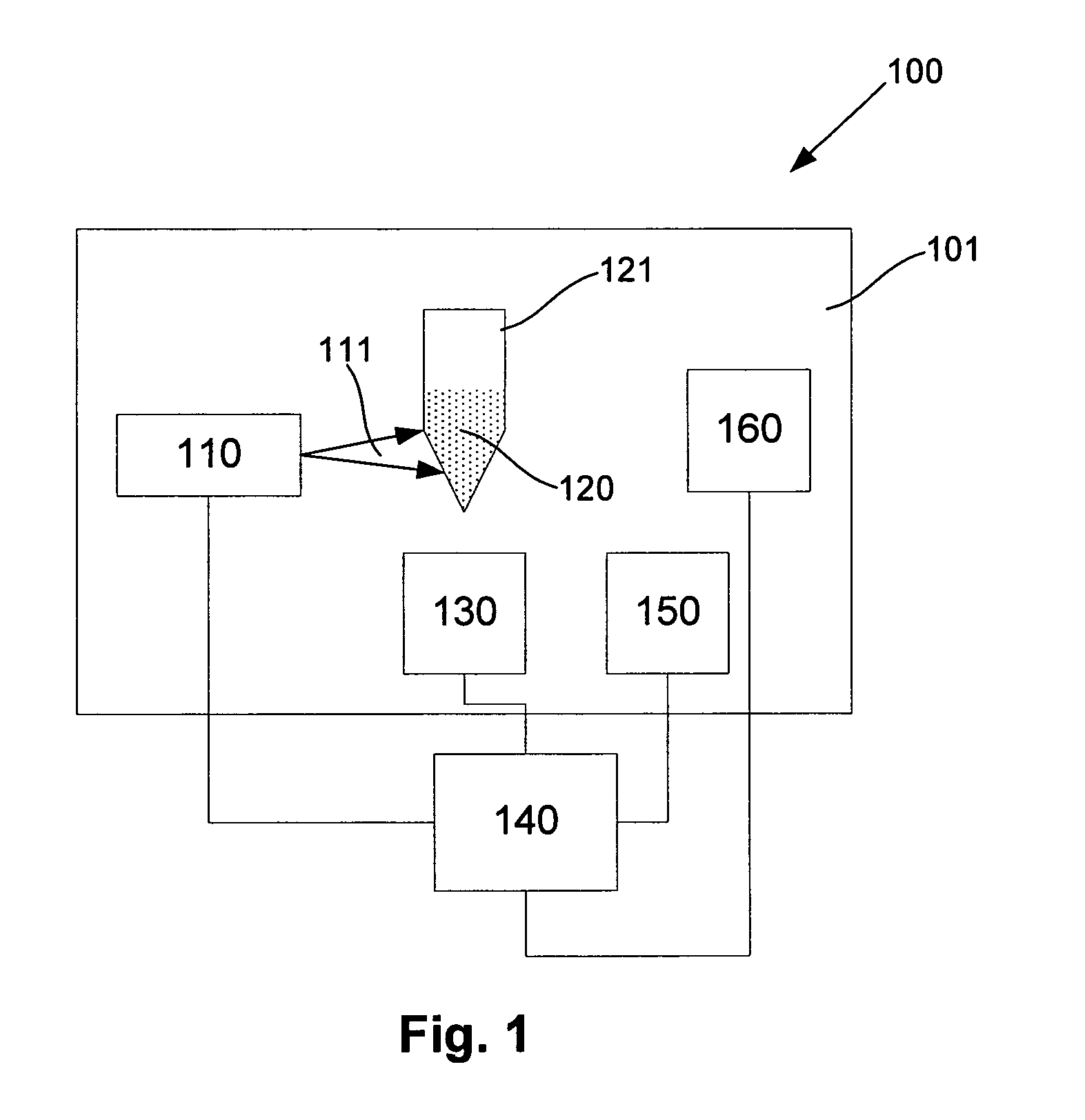
[0087]An example apparatus for controlling the temperature of a reaction mixture held within a reaction container, will now be described with reference to FIG. 1.

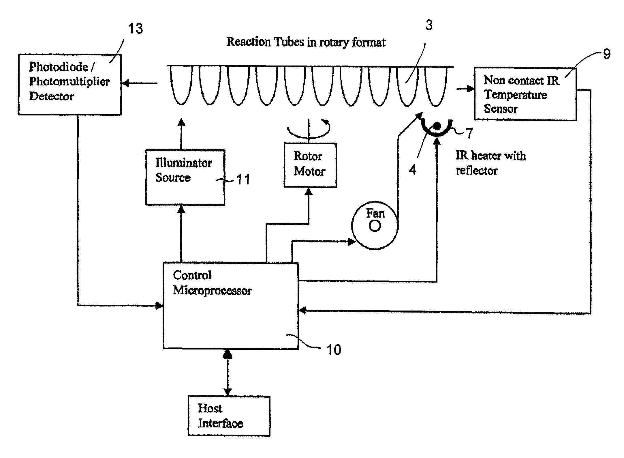
[0088]In this example, the apparatus 100 includes a chamber 101 containing a radiation source 110 for exposing a reaction container 121 to radiation thereby heating a reaction mixture 120 provided therein. The radiation source may be any suitable form of radiation source, but is typically in the form of an infra-red heater for generating infra-red radiation. However, in other examples, one or more lasers, light emitting diodes (LEDs), or the like can be used to generate optical or infra-red radiation. The radiation can be used to heat the reaction container, which in turn heats the reaction mixture.

[0089]Alternatively the radiation may heat one or more components in the reaction mixture directly, for example, if ...


PUM

PropertyMeasurementUnit
temperatureaaaaaaaaaa

Abstract

Apparatus for controlling the temperature of a reaction mixture held within a reaction container, the apparatus including a radiation source for exposing the reaction container to radiation thereby heating the reaction mixture, a temperature sensor for sensing a temperature indicative of a reaction mixture temperature and a controller for controlling the radiation source in accordance with the reaction mixture temperature to thereby selectively heat the reaction mixture.

Description

CROSS REFERENCE TO RELATED APPLICATIONS[0001]This application is a §371 national stage of PCT / AU2008 / 001752 filed Nov. 27, 2008, which claims priority to Australian Application 2007906569 filed Nov. 30, 2007.FIELD OF THE INVENTION[0002]The present invention relates to apparatus and a method for controlling the temperature of a reaction mixture and in particular to thermal cycling devices for nucleic acid amplification. However, it will be appreciated that the invention is not limited to this particular field of use.BACKGROUND OF THE INVENTION[0003]The reference in this specification to any prior publication (or information derived from it), or to any matter which is known, is not, and should not be taken as an acknowledgment or admission or any form of suggestion that the prior publication (or information derived from it) or known matter forms part of the common general knowledge in the field of endeavour to which this specification relates.[0004]PCR is a technique involving multipl...

Claims


Application Information

Patent Timeline
Patent Type & Authority Patents(United States)
IPC IPC(8): B01L5/00C40B60/00C12M1/38B01L3/00B01L7/00H05B6/00B01L9/06
CPCB01L7/5255B01L3/50851B01L7/52B01L9/06B01L2200/147B01L2300/0803B01L2300/1844B01L2300/1861B01L2300/1872B01L2300/1894
Inventor CORBETT, JOHN
Owner QIAGEN GMBH
Why Eureka
Try Eureka