Multifunction test instrument probe

a multi-functional, test instrument technology, applied in the direction of instruments, electrical testing, measurement devices, etc., can solve the problems of requiring two hands, risking equipment damage or even personal injury, and achieve the effect of minimal distraction

Active Publication Date: 2016-03-01
CHAIT PAUL NICHOLAS +1
View PDF8 Cites 3 Cited by
  • Summary
  • Abstract
  • Description
  • Claims
  • Application Information

AI Technical Summary

Benefits of technology

[0015]It is another object of the present invention to provide a new and improved test instrument probe that can perform electrical testing with a minimum of distractions caused by changing probes.

Problems solved by technology

The changing to a different tip from that already on the probe, which in practice is often unavailable due to being lost or misplaced, requires two hands, consumes time, and can result in accidents.
For example, to avoid the inconvenience of retrieving and installing the appropriate probe or tip, the operator may continue to work with the existing configuration, risking equipment damage or even personal injury.

Method used


Image

  • Multifunction test instrument probe
  • Multifunction test instrument probe
  • Multifunction test instrument probe

Examples


Embodiment Construction

[0041]Referring to FIGS. 1 through 10, wherein like reference numerals refer to like components in the various views, there is illustrated therein a new and improved multifunction test instrument probe, generally denominated 100 herein.

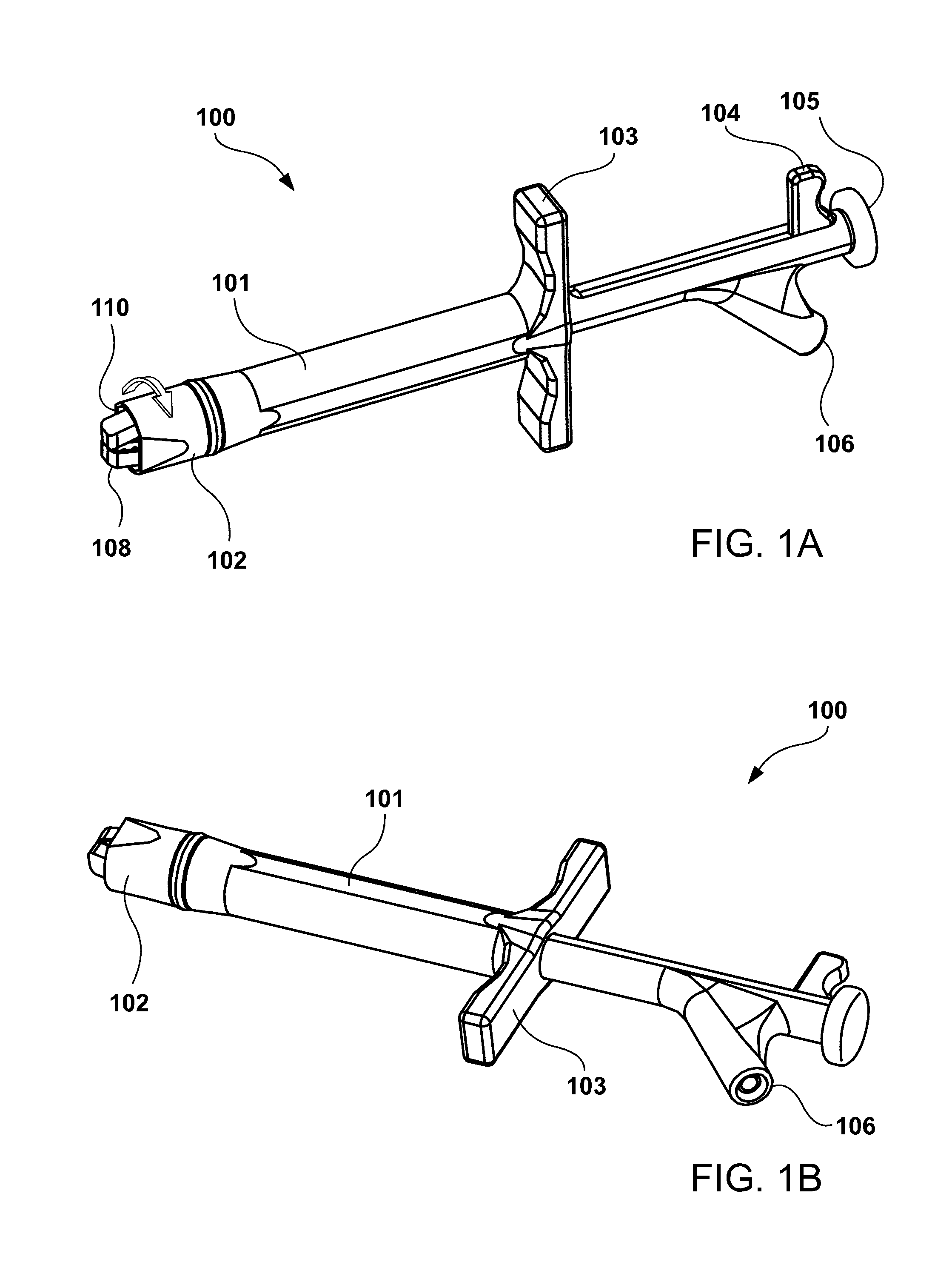
[0042]FIG. 1A is a front perspective view of a first preferred embodiment of the probe 100 at rest, comprising probe housing 101, manually rotatable end 102, finger grip 103, point thumb press 104, clamp thumb press 105, and test lead socket 106. In this view of the probe at rest, both the alligator clamp and point portions of the probe are retracted within the housing, with only the distal end of the alligator clamp 108 visible through open end 110 of the housing. The housing 101 may be of any appropriate shape, including cylindrical, square, rectangular, or multifaceted.

[0043]FIG. 1B is a lower perspective view of the probe 100 illustrating the test lead socket 106, which provides a receptacle for a test wire lead plug.

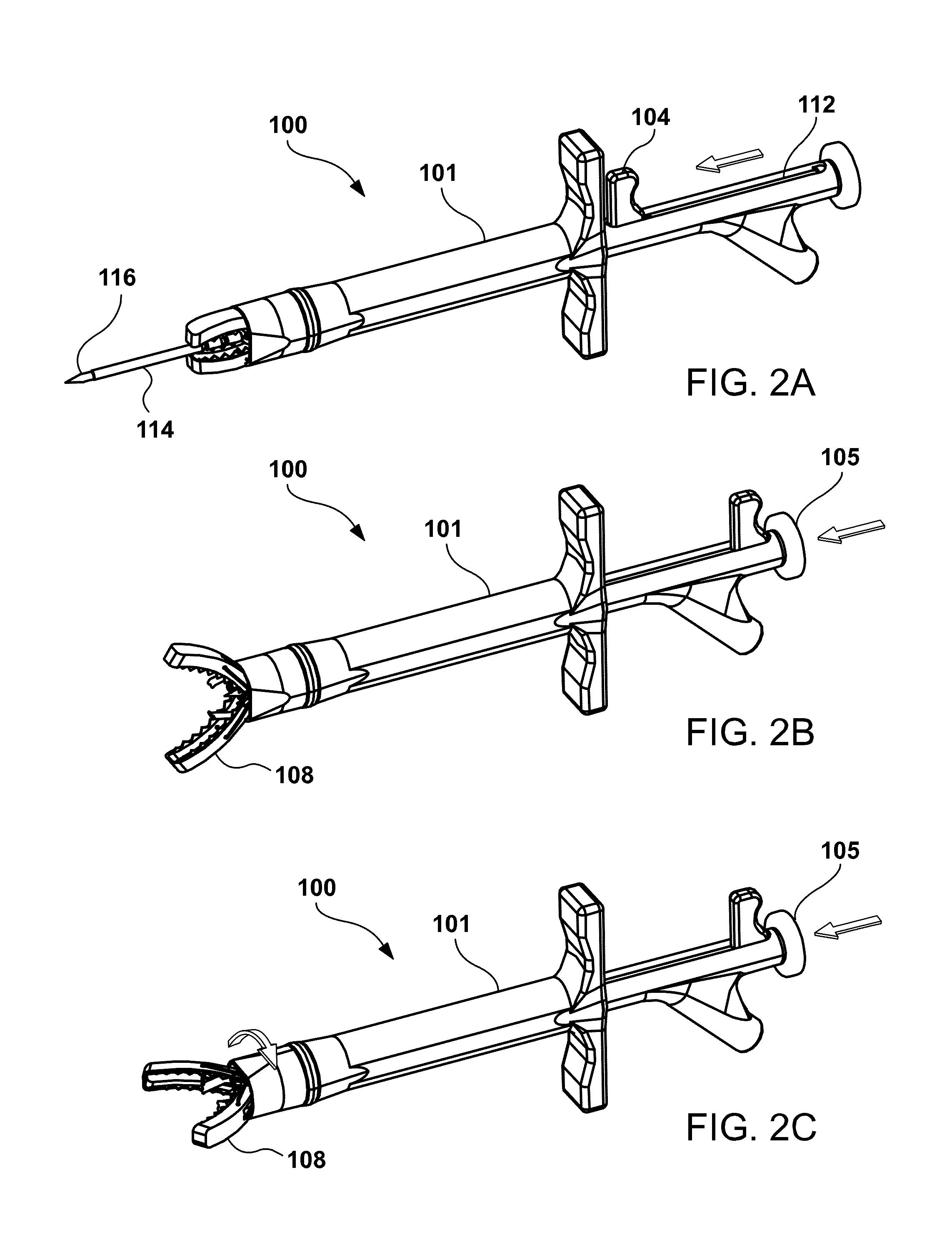
[0044]FIG. 2A is a front persp...


PUM


Abstract

A multifunction test instrument probe includes a housing having a hollow bore with an open end. A clamp plunger is carried in the hollow bore, with a first end including a thumb press, and a second end including an alligator clamp having a pair of jaws, with a compression spring normally biasing the thumb press away from the housing, and normally biasing the alligator clamp substantially within the hollow bore proximate the open end. A point plunger is also carried in the bore, with a first end including a thumb press, and a second end terminating in a point, with a second compression spring normally biasing the thumb press away from the housing, and biasing the point within the hollow bore proximate the open end. When the clamp plunger is depressed, the alligator clamp is extended from the open end and the jaws are urged open by a jaw spring, and when the clamp plunger is released, the compression spring acts to retract the alligator clamp back towards the hollow bore and the jaws are urged closed by contact with the open end. When the point plunger is depressed, the point is extended from the open end. When the clamp plunger is again depressed, the point retracts into the housing.

Description

CROSS REFERENCE TO RELATED APPLICATIONS[0001]The present application is a continuation-in-part of U.S. patent application Ser. No. 13 / 838,547, filed Mar. 15, 2013, now U.S. Pat. No. 8,922,196, issued Dec. 30, 2014, and which claims the benefit of the filing date of U.S. Provisional Patent Application Ser. No. 61 / 613,169, filed Mar. 20, 2012. The foregoing applications are incorporated by reference in their entirety as if fully set forth herein.STATEMENT REGARDING FEDERALLY SPONSORED RESEARCH OR DEVELOPMENT[0002]Not applicable.REFERENCE TO A MICROFICHE APPENDIX[0003]Not applicable.TECHNICAL FIELD[0004]The present invention relates generally to electrical test instrument probes, and more particularly, to probes which incorporate two different types of tips within one probe.BACKGROUND INFORMATION AND DISCUSSION OF RELATED ART[0005]Test instruments such as AC Voltmeters, DC Voltmeters, Ammeters and Ohmeters are all used for measuring the numerical value of their respective functions. Al...

Claims


Application Information

Patent Timeline
Patent Type & Authority Patents(United States)
IPC IPC(8): G01R1/06G01R1/067G01R1/073
CPCG01R1/07364G01R1/06788
Inventor CHAIT, PAUL, NICHOLASCHAIT, STANLEY
Owner CHAIT PAUL NICHOLAS
Why Eureka
Try Eureka