Orifice holder and tube assembly for use with a gas-fueled appliance

a technology for gas-fueled appliances and tube assemblies, which is applied in the direction of combustion control, combustion types, domestic stoves or ranges, etc., can solve the problems of not controlling two burners as a unit, difficult to achieve uniform heating of the griddle,

Active Publication Date: 2016-03-29
HAIER US APPLIANCE SOLUTIONS INC
View PDF3 Cites 13 Cited by
  • Summary
  • Abstract
  • Description
  • Claims
  • Application Information

AI Technical Summary

Problems solved by technology

As such, it may be difficult to achieve uniform heating of the griddle.
However, known cooktops do not control two burners as a unit because such cooktops include a one-to-one valve-to-burner ratio.

Method used


Image

  • Orifice holder and tube assembly for use with a gas-fueled appliance
  • Orifice holder and tube assembly for use with a gas-fueled appliance
  • Orifice holder and tube assembly for use with a gas-fueled appliance

Examples


Embodiment Construction

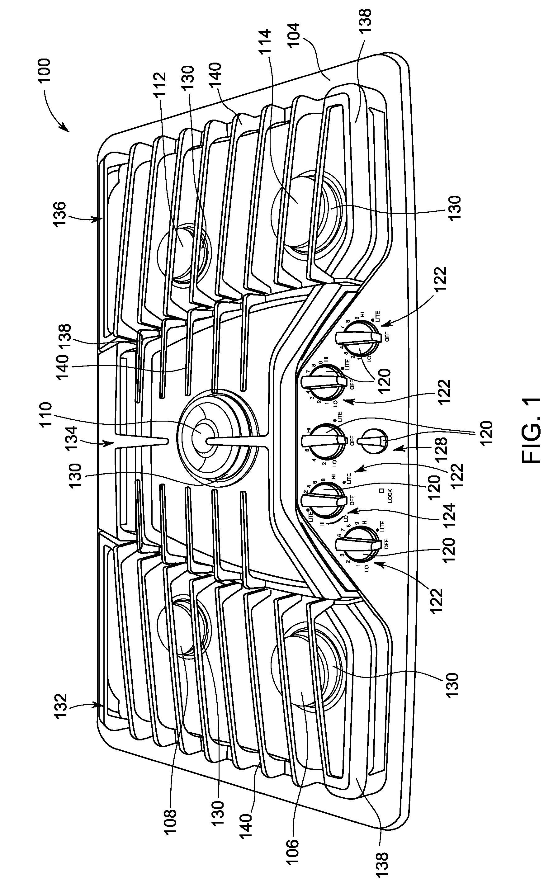
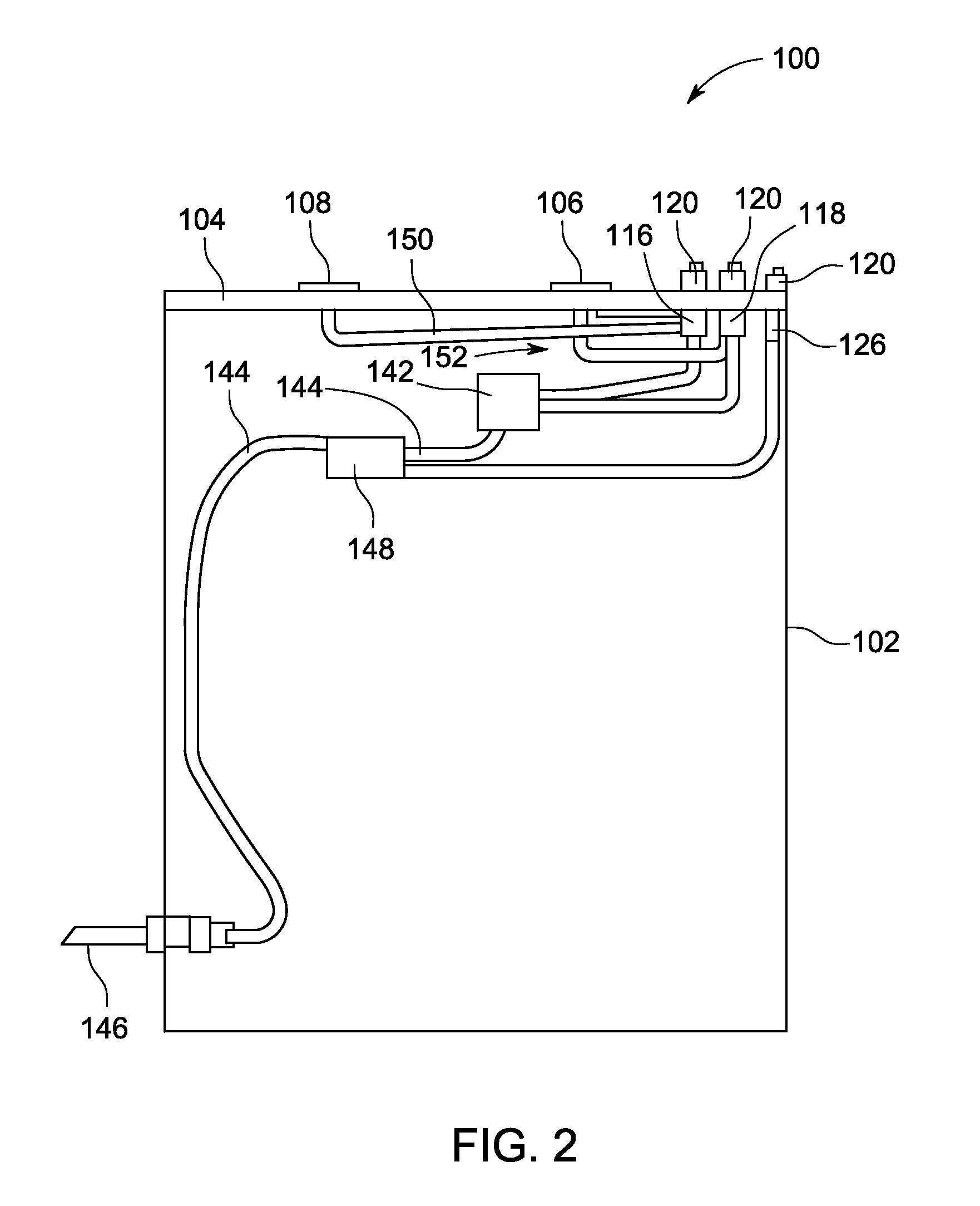
[0019]The embodiments described herein enable a gas-fueled cooking appliance to be operated in a normal mode and a griddle mode. As used herein, the “normal mode” refers to a mode in which each burner of the cooking appliance is operated independently, and the term “griddle mode” refers to a mode in which a plurality of burners are operated together as a unit. A griddle is not required during the griddle mode. Rather, a griddle is referred to herein for convenience. The herein-described embodiments enable one burner to be coupled to at least two different valves to operate in at least two different modes. However, one of the two valves is coupled to at least two burners to operate the burners simultaneously. As such, a user of the cooking appliance is provided with the same number of valve knobs and burners.

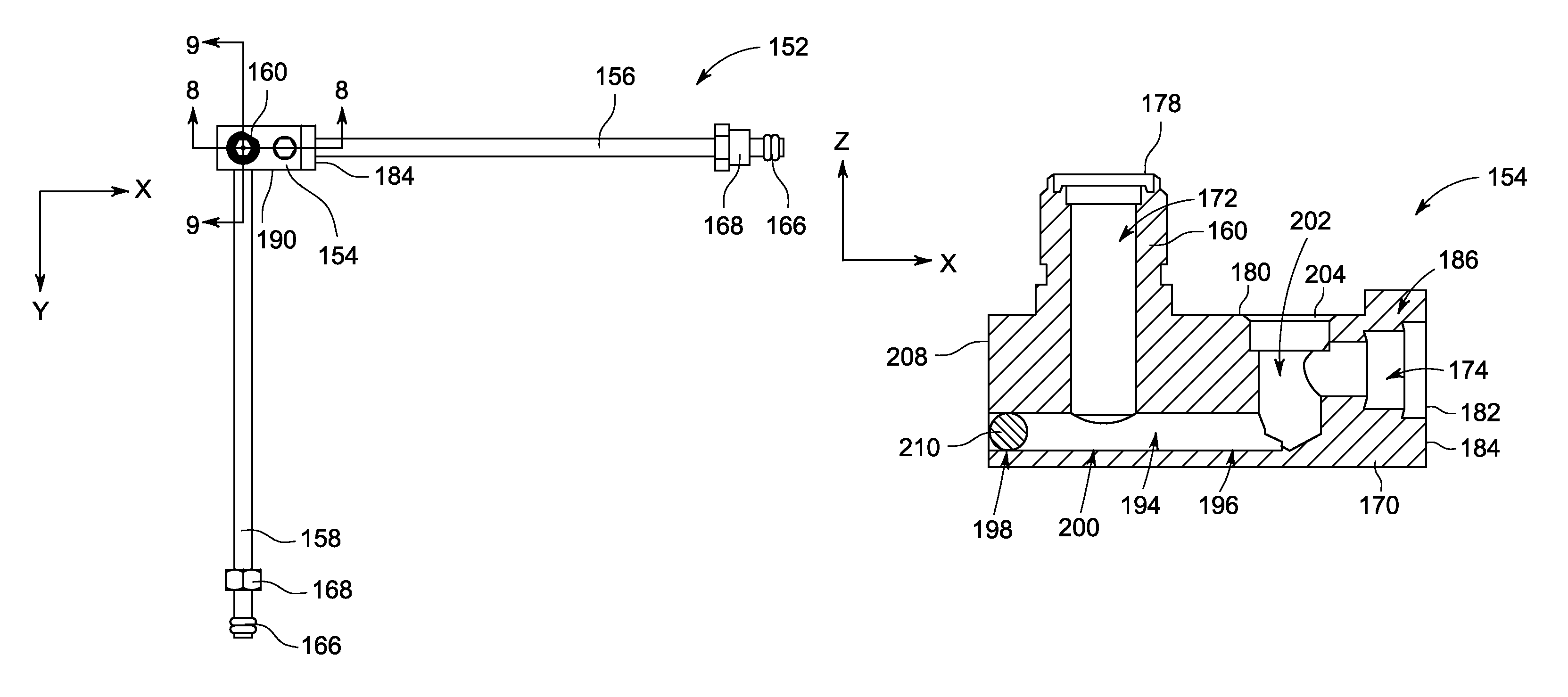
[0020]Further, the tube assembly described herein includes an orifice holder that is coupled to at least two gas supplies, without using another separate component between the ga...


PUM


Abstract

An orifice holder for use with a gas-fueled appliance includes a body, an orifice passage defined in the body, a first tube passage defined in the body, and a second tube passage defined in the body. The orifice passage, the first tube passage, and the second tube passage are in flow communication within the body.

Description

BACKGROUND OF THE INVENTION[0001]The embodiments described herein relate generally to a tube assembly and, more particularly, to a tube assembly for use with a gas-fueled appliance.[0002]At least some known gas-fueled cooktops include a pair of burners that can be used with a griddle, rather than grates. More specifically, the grates are removed and the griddle is positioned over the pair of burners. As such, both burners are activated to heat the entire griddle. One known cooktop includes valves that independently control each burner. When the griddle is used with the cooktop, each burner under the griddle is controlled independently. As such, it may be difficult to achieve uniform heating of the griddle.[0003]Another known cooktop is configured to control the burners below the griddle as a unit. Such a cooktop includes three valves for the two burners. More specifically, a first valve independently controls a first burner, a second valve independently controls a second burner, and...

Claims


Application Information

Patent Timeline
Patent Type & Authority Patents(United States)
IPC IPC(8): F24C3/00F24C3/08F24C3/12F24C15/00F23D14/06F23D23/00F23D14/64
CPCF24C3/08F23D14/06F23D14/64F23D23/00F23D2213/00F23K2900/05002F23N2037/02F23N2237/02
Inventor HENSLEY, AMELIA, LEARTATUM, ALLEN, LOUISMAHANEY, MICHAELKING, SCOTT, RUSSELLNORTHCUT, JASON, RANDALLCOULTER, JEFFREY, SHAWN
Owner HAIER US APPLIANCE SOLUTIONS INC
Why Eureka
Try Eureka