Sun tracking tint visor

a technology of sun tracking and visor, which is applied in the direction of antiglare equipment, vehicle components, transportation and packaging, etc., can solve the problems of temporary blindness, damage to the vehicle, impact and subsequent damage, etc., and achieve the optimal level of luminous transmittance, reduce the effect of flash blindness and other distractions, and reduce the effect of sunshin

Inactive Publication Date: 2016-04-05
GREY MATTER FUSION
View PDF30 Cites 7 Cited by
  • Summary
  • Abstract
  • Description
  • Claims
  • Application Information

AI Technical Summary

Benefits of technology

[0012]At the heart of the preferred embodiment of the invention is a piece of light-transmissible, transparent material wider than it is tall, further comprising a strongly tinted strip portion. In such embodiment, the strongly tinted strip portion is nearly as wide as the more fully light transmissible, transparent material, but much less tall. Said strongly tinted strip portion is also light-transmissible and transparent, although with the approximate darkness of a welding shield. The strongly tinted portion is designed to greatly reduce sunshine from entering the vehicle occupants' eyes (especially the driver's), thus limiting said sun's direct rays from distracting or causing severe impairment to a vehicle's occupants. In an alternative embodiment of the invention, the surrounding light-transmissible tinted filter piece is strongly tinted to block a large amount of light, but lacks the tinting of the super dark tinted strip portion.
[0013]A novel aspect of the invention is the incorporation of more than one tinted region, wherein a more strongly tinted strip portion conforms to American National Standards Institute (ANSI) values corresponding to heavy levels of tinting normally associated with the tinting utilized in welding shields. In the preferred embodiment of the invention, by incorporating a tint that conforms to ANSI standards of tint levels associated with eye protection utilized during welding activities, wherein a small amount of light can pass through the strongly tinted strip portion, the user can more readily readjusted the more strongly tinted strip portion directly in the line of sight between the eyes of the user to the sun to block the sun's direct rays from directly entering into the user's eyes.
[0014]The preferred embodiment of the invention, while never fully opaque, is not only light transmissible, but is also transparent or semi-transparent, to enable the user to continuously observe the surroundings without an obstructed view. The preferred embodiment of the invention also incorporates transparent materials of varying tint level to ensure that an optimal level of luminous transmittance is preserved. Thus, in the preferred embodiment of the invention, the major problem of obstructed forward view associated with opaque visors known in the prior art is solved by preserving a level of transparency to enable a user to maintain a more complete field of view while still dramatically reducing the effects of Flash Blindness and other distractions caused by sunlight. The preferred embodiment of the present invention, therefore, enables its user to simultaneously block dangerous levels of brightness from the sun, track the sun's position, and also maintain spatial awareness of the surroundings of the vehicle through a lesser tinted area, while solving a number of problems associated with related prior art inventions, in a manner that allows for balance between the need to maintain a full field of forward vision, with the need to minimize the distraction and risk caused by sunlight.

Problems solved by technology

Bright rays of sunshine encountered on the road can distract drivers, even potentially temporarily blinding them.
Poor visibility caused by sunshine can lead to loss of control of the vehicle, impact and subsequent damage to the vehicle and injury or death of drivers, passengers, or onlookers.
Sunshine faced while occupying a vehicle can cause pain or irritation to the eyes of occupants of a vehicle, or potential long-term damage to eyesight.
A major problem associated with opaque visors known in the prior art is that they obstruct the view of the occupants of a vehicle, and most critically, the driver of a vehicle.
Users can “peek” around the visor to observe said obstacles or hazards, but if the user by chance looks directly at the sun, “peeking” may lead to momentary flash blindness caused by bright sunshine.
The problem of the hazards associated with peeking is exacerbated by the opaque visors known in the prior art, as the user of such devices do not know where the sun may enter into their line of sight from behind the visor.
As such, such a user may peek around an opaque visor only to suddenly and unintentionally look directly into the sun.
The flash blindness caused by such an action could prove catastrophic for the operator of a vehicle.
As a result of such flash blindness, a vehicle operator could wreck the vehicle, damage exterior objects, or worse potentially cause injury or death to individuals either outside of the vehicle or occupants of the vehicle.
Flash blindness and / or a bright sun are also problematic for general driving.
Sun glare—the very bright shine associated with the sun during certain times of the day, weather conditions, climates, and / or seasons—can have adverse effects on the driver.
There are numerous reports of traffic accidents solely or partly attributed to glare associated with the sun and related light reflected from various reflective surfaces.
Traffic can increase commute time, increase air pollution, and decrease productivity.
Finally, dealing with sun glare may cause fatigue in individuals in a vehicle, especially the driver, during exposure to the sun light and / or associated traffic.
The scope of sunshine protection offered by prior art visors is limited in a number of ways.
Thus, such reflected light can easily cause distractions to vehicle occupants as does direct rays of light from the sun.
Prior art visors can also be problematic for some people of certain sizes and for some configurations of internal vehicular seating in relation to a windshield.
However, in some cases, prior art visors may not be effective for users of below average stature, due to the location and angle of the sunshine relative to their eye level, for example, when the sun is near the horizon.
Prior art visors may also not be ideal for users of above average stature, as current opaque visors may obstruct and reduce visibility of the road for said users of above average stature.
Moreover, prior art visors may work well only for certain configurations of vehicular seating in relation to a windshield.
If a seat is too far away from or too close to a windshield, the angle of the sunshine entering into a car, whether direct or reflected, prevents many traditional prior art visors from offering adequate sunshine protection in such instances.
Such devices, however, have their own disadvantages.
Even when prior art devices can be used independently of the position of traditional visors, they suffer the same issue of the inability to track the sun's movement.
Moreover, while many such prior art devices attempt to solve the problem of visibility by incorporating a tint, the tint is inadequate.
A primary problem associated with many tint-incorporating transparent or semi-transparent visors known in the prior art is that the tint utilized by such visors does not adequately reduce intensity of sunlight.
As such, if a driver intentionally or unintentionally looks through a prior art visor incorporating such low tint levels directly into the sun, the driver would experience flash blindness causing the risk of harm or death to either the driver, occupants of the vehicle, or individuals outside of the vehicle.

Method used


Image

  • Sun tracking tint visor
  • Sun tracking tint visor
  • Sun tracking tint visor

Examples


embodiment 3

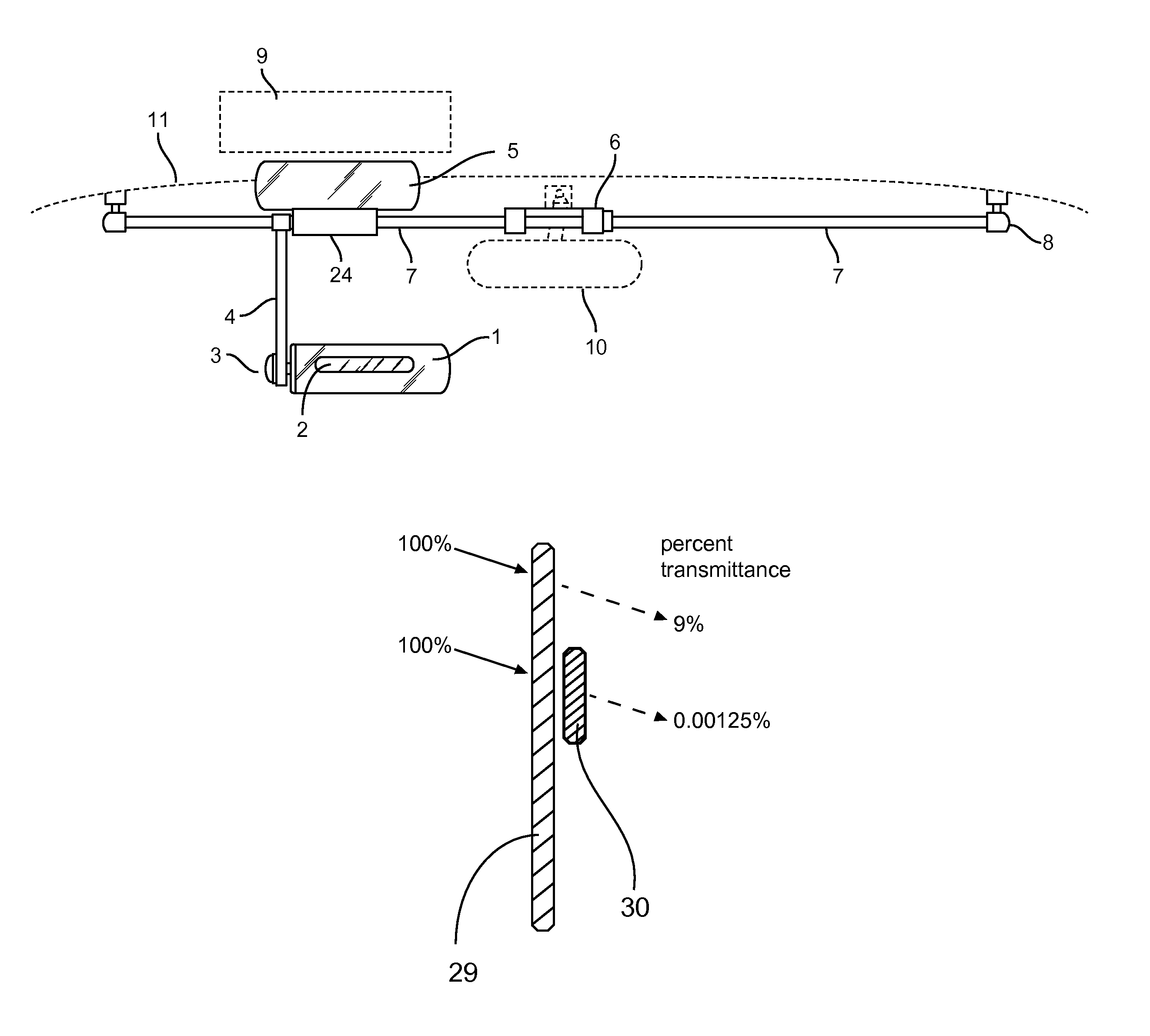
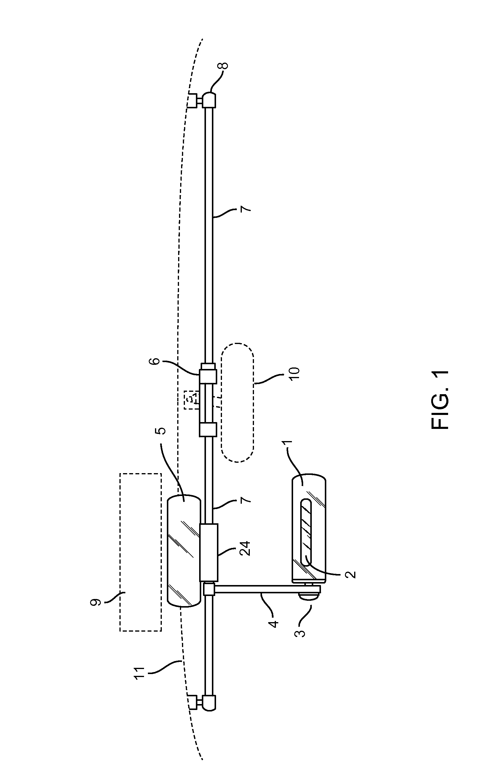
[0093]In addition, the user can move the Optical Filter 1 and Darker Tint Strip 2 in a general vertical direction, such as, for example, using an arm. Said arm, hereinafter referred to as “Track Arm”4, is the attachment between the Optical Filter 1 and Darker Tint Strip 2 and the Track Rod 7. In the preferred embodiment of the invention, the Track Arm 4 will move the Optical Filter 1 and Darker Tint Strip 2 in the vertical direction (as illustrated in FIG. 8B). In addition, the Track Arm 4 will contain other components, including, but not limited to hinges, ball and socket joint, spring, piston, slides, etc. that afford the user of the Optical Filter 1 and Darker Tint Strip 2 mobility in a multitude of directions. For instance, the Optical Filter 1 and Darker Tint Strip 2 are secured to the Track Arm 4 by an Optical Filter Adjustment embodiment 3, as depicted in the embodiment in FIG. 16. In such specific embodiment, the Optical Filter Adjustment secures the Optical Filter 1 and Dar...

embodiment 5

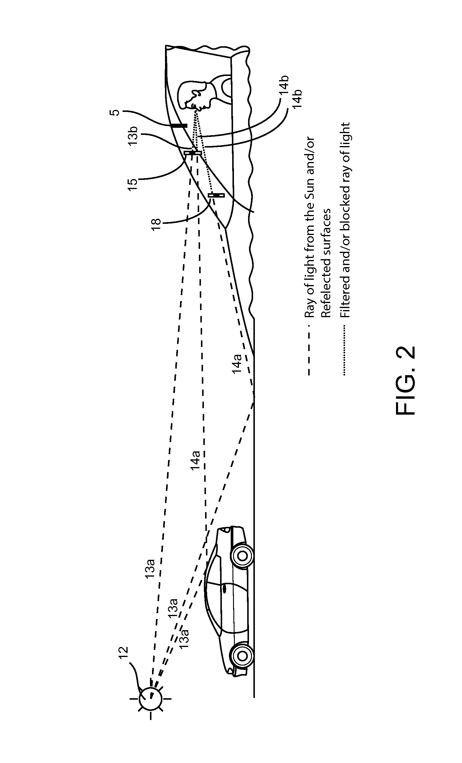
[0096]In another situation, in which the sun 12 is at a high position relative to the horizon the present invention is also beneficial for a user. As depicted in FIG. 3, the Optical Filter and Darker Tint Strip assembly embodiment can be positioned in front of a user to filter out various rays of reflected light while using an Auxiliary Darker Visor Embodiment 5 to filter the ray of light 13B from other sources, such as the sun 12. Various surfaces can reflect the rays of light from the sun 12 in varying intensities. The user can utilize the preferred embodiment of the Optical Filter and Darker Tint Strip assembly to block these various rays of light. For instance, a reflected ray of light from a highly-reflective surface 16A, wherein said highly-reflective surface includes, for example, certain portions of another vehicle's windshield or metallic surface, can be filtered by the Darker Tint Strip 16B. At the same time, a reflected ray of light from another surface 14A, can be filter...

embodiment 24

[0128]In addition, the inventor has recognized that the resistance force to move the Sun-Tracking Tint Visor is an important component of the preferred embodiment of the present invention. Such resistance force is needed to ensure that the Optical Filter 1, Darker Tint Strip 2, Track Rod 7, Track Arm 4, and / or other moving components comprising the preferred embodiment of the invention do not unintentionally move during acceleration, deceleration, and turning. In an embodiment, the hinges, ball and socket joint, spring, piston, slides, cables, pulleys, belts and / or other components that afford movement of the Optical Filter 1 and / or Darker Tint Strip 2 can be user-tightened with, such as for example, a clamp and / or tightening screw mechanism. Said tightening screw mechanism may be user-adjusted and / or spring-loaded. Such said user-adjusted tightening mechanism is represented in an illustration in FIG. 12 showing an embodiment of the Sliding Carriage Box. The Sliding Carriage Box emb...


PUM


Abstract

A light filtering transparent or semitransparent visor intended to prevent flash blindness and other hazards associated with the adverse affects associated with bright lights impacting the eyesight of occupants of a vehicle. In the preferred embodiment of the invention, the visor comprises a larger, tinted body surrounding a smaller, much more heavily tinted body intended to filter the bright rays of sun to enable safe viewing of the sun through the filter. The entire apparatus is designed to be repositioned directly in the line of sight between the viewer and the sun in the preferred embodiment of the invention.

Description

CROSS-REFERENCE TO RELATED APPLICATIONS[0001]Not ApplicableSTATEMENT REGARDING FEDERALLY SPONSORED RESEARCH OR DEVELOPMENT[0002]Not ApplicableREFERENCE TO SEQUENCE LISTING, A TABLE, OR A COMPUTER PROGRAM LISTING COMPACT DISK APPENDIX[0003]Not ApplicableBACKGROUND OF THE INVENTION[0004]Safe operation of a vehicle requires a clear, unimpaired view out of the vehicle. Bright rays of sunshine encountered on the road can distract drivers, even potentially temporarily blinding them. Poor visibility caused by sunshine can lead to loss of control of the vehicle, impact and subsequent damage to the vehicle and injury or death of drivers, passengers, or onlookers. Sunshine faced while occupying a vehicle can cause pain or irritation to the eyes of occupants of a vehicle, or potential long-term damage to eyesight.[0005]Traditional visors in the prior art (DE102005025089A1, DE 3436760C1) are rectangular devices that are installed in vehicles, usually during the process of manufacturing the vehi...

Claims


Application Information

Patent Timeline
Patent Type & Authority Patents(United States)
IPC IPC(8): B60J3/04B60J3/02
CPCB60J3/04B60J3/0239B60J3/0208
Inventor KIM, PHILOS
Owner GREY MATTER FUSION
Why Eureka
Try Eureka