Door rail system

Active Publication Date: 2016-04-05
CHOI KEVIN BYONG SUN
View PDF10 Cites 16 Cited by
  • Summary
  • Abstract
  • Description
  • Claims
  • Application Information

AI Technical Summary

Benefits of technology

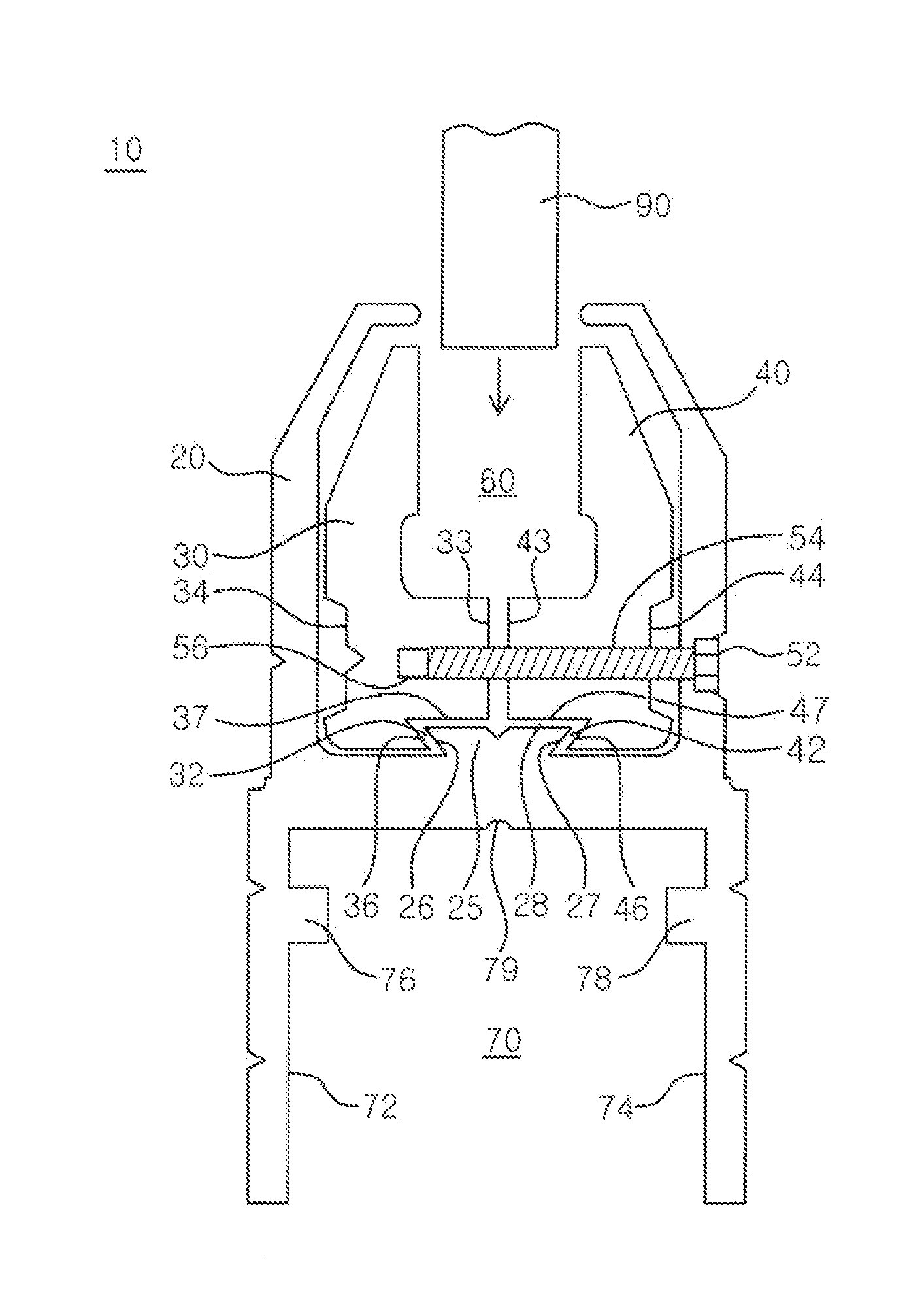
The present invention provides a door rail system for mounting a pane that includes a clamp housing and a pair of clamps with symmetrical recesses and a tapered projection for securely holding a pane at a center without tilting. The system also has adjustable fastening means and mounting members that enable easy and convenient assembly and adjustment of the system without dissembling it from the door. Additionally, the system has slidably attachable side covers that provide aesthetic appearance.

Problems solved by technology

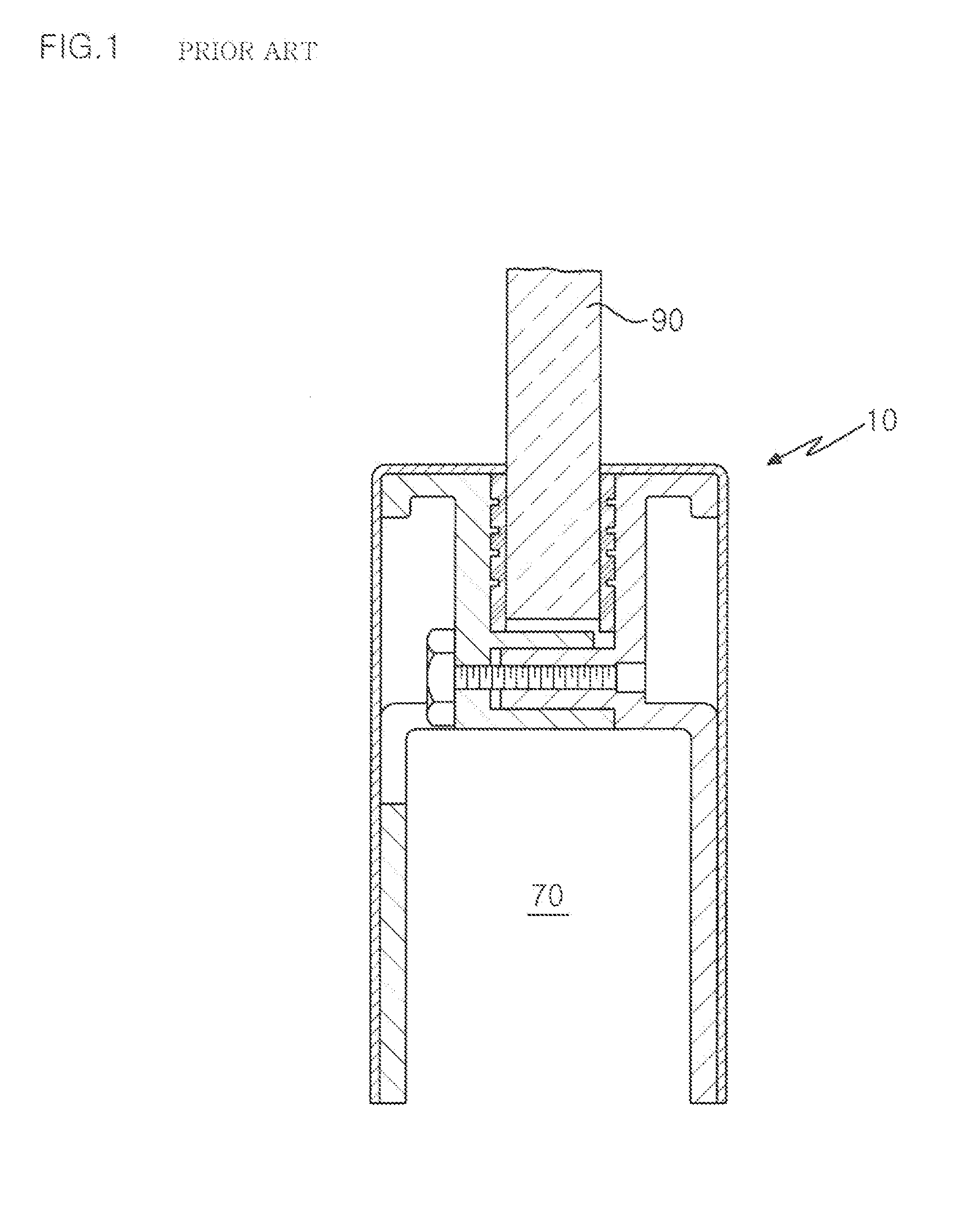
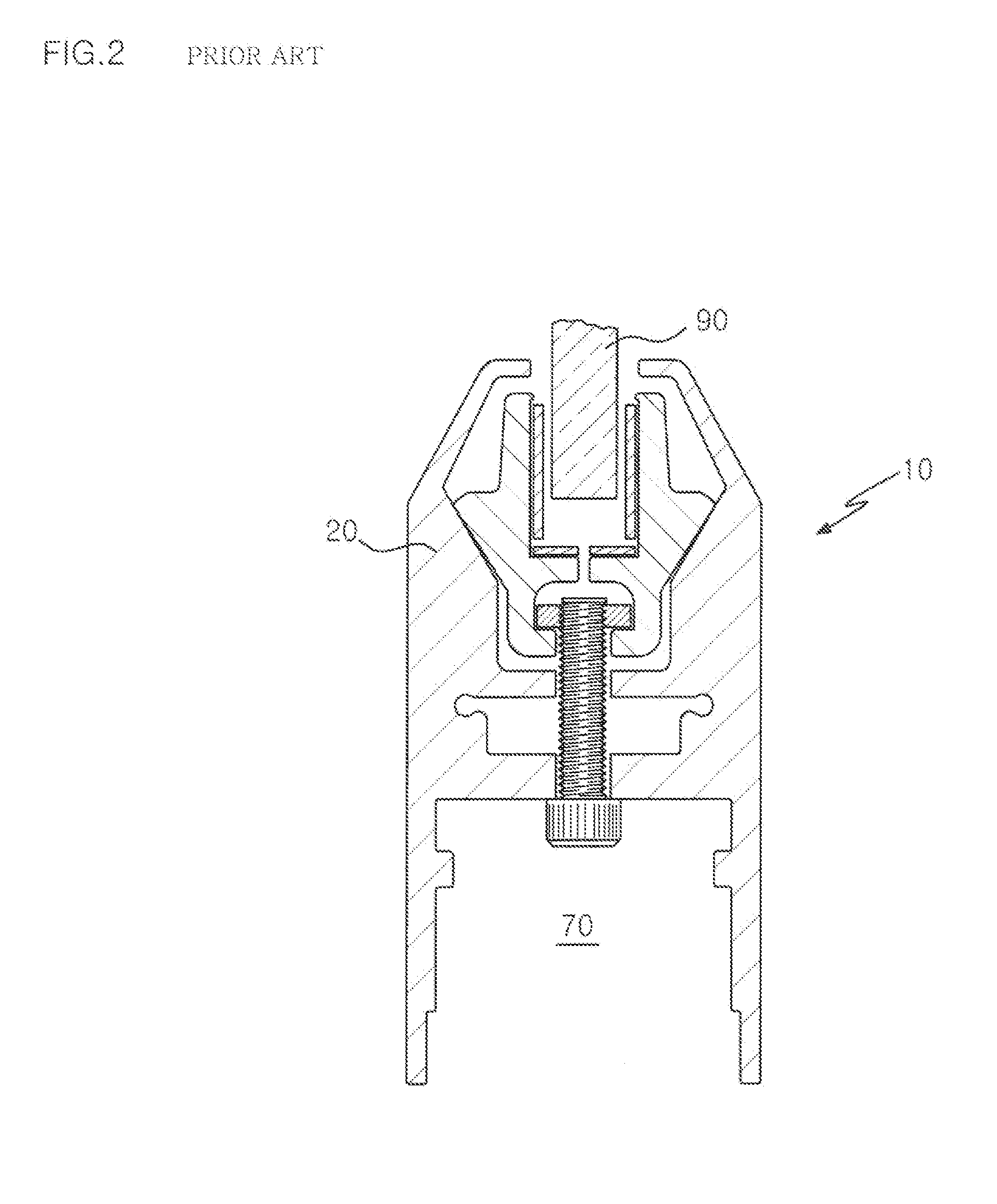
However, rotating a screw from a bottom is inconvenient and the rail system 10 has to be dissembled from a door or other frame before dissembling the pane90.
Besides, conventional door rail systems requires careful work of mounting such system to a door.
However, slight discrepancy or error is very common and accordingly re-work is common.

Method used


Image

  • Door rail system
  • Door rail system
  • Door rail system

Examples


Embodiment Construction

[0022]Reference will now be made in detail to the preferred embodiments of the present invention, examples of which are illustrated in the accompanying drawings, which form a part of this disclosure. It is to be understood that this invention is not limited to the specific devices, methods, conditions or parameters described and / or shown herein, and that the terminology used herein is for the purpose of describing particular embodiments by way of example only and is not intended to be limiting of the claimed invention.

[0023]Also, as used in the specification including the appended claims, the singular forms “a”, “an”, and “the” include the plural, and reference to a particular numerical value includes at least that particular value, unless the context clearly dictates otherwise. Ranges may be expressed herein as from “about” or “approximately” one particular value and / or to “about” or “approximately” another particular value. When such a range is expressed, another embodiment includ...


PUM


Abstract

A door rail system for mounting a pane includes a clamp housing having a tapered projection and a pair of clamps having a recess. A screw fastens the clamps together from a side of the clamp housing so that the recesses and tapered projection are configured to form a secure dovetail joint for holding a pane. The recesses (and clamps) are symmetrical and the tapered projection is at the center so that a pane can be securely held at the center without being tilted. The door rail system includes an accessory channel and first and second mounting members. The first and second mounting members are slidably attached to each other by a sliding dovetail joint so that each mounting member can slide against the other mounting member.

Description

FIELD OF THE INVENTION[0001]The present invention relates to a door rail system for holding a pane such as plate glass panes or panels and, more particularly, to a door rail system having a pair of clamps having recesses and a clamp housing having a tapered projection. The recesses and tapered projection are configured to form a dovetail joint when the clamps are clamped together.BACKGROUND OF THE INVENTION[0002]Door rail systems are widely used to hold plate glass panes or panels, including transparent, translucent or opaque panels (hereinafter called “pane”) and such systems employs support rails or similar frames which attach to the top or bottom edges of the pane.[0003]FIG. 1 shows a prior art rail system 10 having a male rail section and a female rail section. The male and female sections are clamped together by a screw to hold a pane 90 and to form an accessory channel 70. The accessory channel 70 is necessary to mount a door closure member, locking hardware, pivots, hinges or...

Claims


Application Information

Patent Timeline
IPC IPC(8): E04C2/38E06B3/54E06B5/00E06B7/28
CPCE06B3/549E06B3/5454E06B5/00E06B7/28E06B3/4609E06B3/585E06B3/5878E06B3/60
Inventor CHOI, KEVIN BYONG SUN
Owner CHOI KEVIN BYONG SUN
Why Eureka
Try Eureka