Switching device

a switching device and low-voltage technology, applied in the direction of air-breaking switches, high-tension/heavy-dress switches, electrical equipment, etc., can solve the problems of increasing the voltage drop over the separated contacts, breaking the electrical current,

Active Publication Date: 2016-04-26
ABB (SCHWEIZ) AG
View PDF11 Cites 2 Cited by
  • Summary
  • Abstract
  • Description
  • Claims
  • Application Information

AI Technical Summary

Benefits of technology

[0004]The object of the present invention is to provide a low-voltage switching device capable of guiding arc-extinguishing plates into an arc-extinguishing chamber and preventing the arms of the arc-extinguishing plates from damage caused by arcs.
[0005]These objects are achieved by a low-voltage switching device. The low-voltage switching device is further characterized in that the guiding means comprises a plurality of supporting plates. The supporting plates are arranged protruding towards interior of the arc-extinguishing chamber for receiving the arms of the arc-extinguishing plates and for providing electrical isolation between arms of two adjacent arc extinguishing plates. In this way, the arms of each of the arc-extinguishing plates are isolated from each other and the arc is prevented from standing between the arms. This reduces the risk of re-ignition and damage of the arms.
[0006]It is advantageous that the supporting plates are arranged on the sidewalls since the free space between the arms of the arc-extinguishing plates and the contacts makes it possible that the arms of the arc-extinguishing plates may be arranged closer to the contacts. Therefore, forces on the arcs are increased so that the arcs are distinguished efficiently.
[0007]A further advantage is that it makes possible to have a relative wider arms of the arc-extinguishing plates, which attracts the arcs more efficiently so that the arcs move to the arc-extinguishing chamber directly and quickly.
[0010]According to one embodiment of the invention, the low-voltage switching device further comprises a base part and an arc-extinguishing chamber is detachably mounted to the base part. One advantage with a detachably mountable arc-extinguishing chamber is that separation of manufacturing of the base part and the chambers. Therefore, an arc-extinguishing chamber may be produced as modular, which may further reduce the manufacturing cost of a low-voltage switching device.
[0011]Alternatively, an arc-extinguishing chamber is moulded on the base part, in this way the sidewalls are further strengthened by the integrated arc-extinguishing chamber.

Problems solved by technology

When an arc is attracted into the arc-extinguishing chamber, it is further divided into several shorter arcs by the arc-extinguishing plates, which increases the voltage drop over the separated contacts and consequently breaks the electrical current.

Method used


Image

  • Switching device
  • Switching device
  • Switching device

Examples


Embodiment Construction

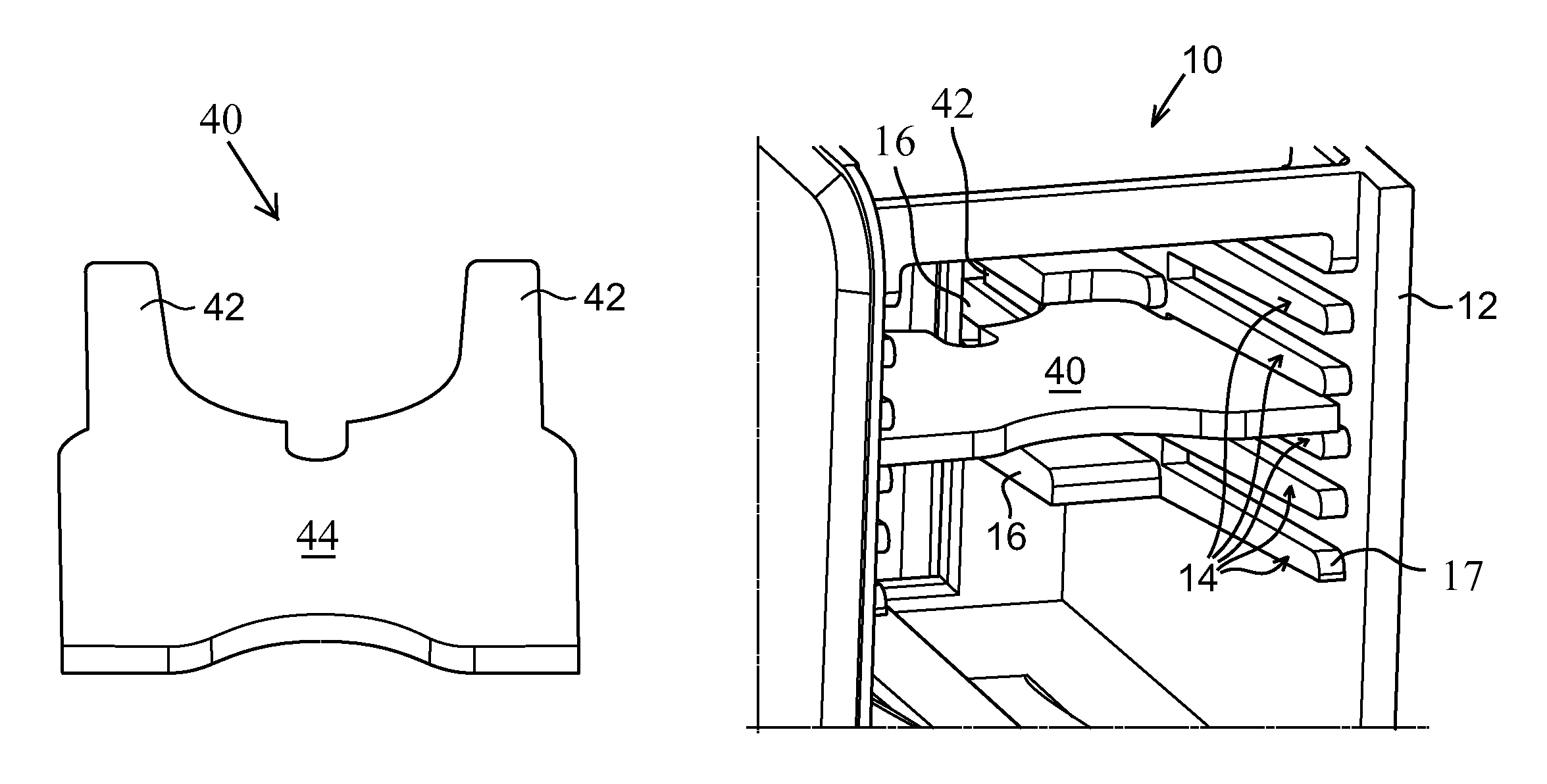
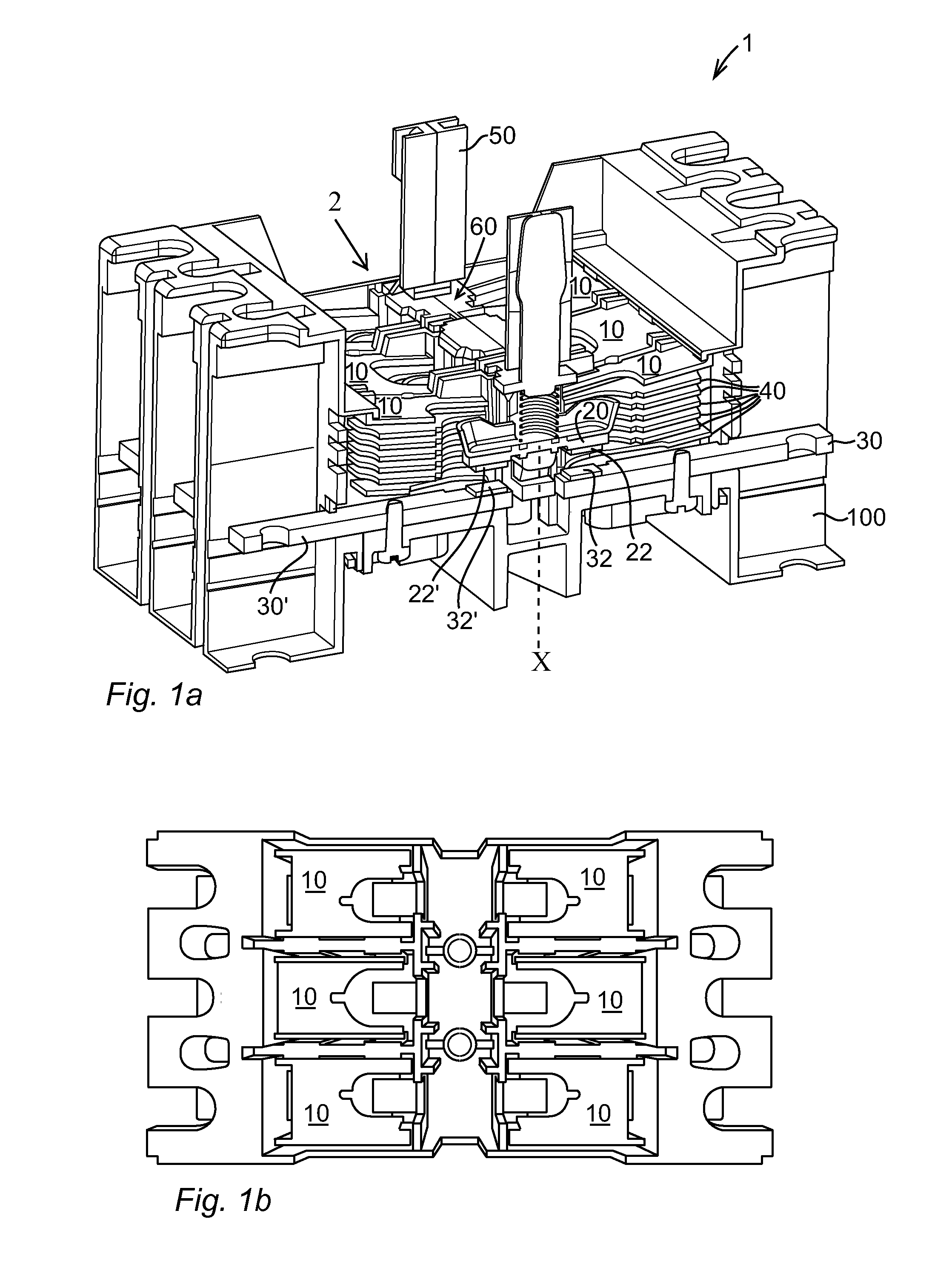
[0020]FIGS. 1a and 1b show a contactor 1 including a switching device 2 and a base part 100. The switching device 2 further comprises a plurality of arc-extinguishing chambers 10, a contacting unit 60 including a stationary contact member 30 and a movable contact member 20 and a contact carrier 50 connected to an actuating unit (not shown in the Figures).

[0021]In this example, the contactor is a three pole contactor with three contacting units to be connected to each of the three phases of a three-phase electric load. Each of the three contacting units includes a movable contact member 20 including two contact pads 22, 22′ and two stationary contact members 30, 30′ situated on the base part 100. The two stationary contact members 30, 30′ are situated in align with the movable contact member 20. The contact pads 22, 22′ are sited at each end of the movable contact member 20. Each of the stationary contact members 30, 30′ is provided with a contact pad 32, 32′ arranged to be cooperate...


PUM


Abstract

A low-voltage switching device including a plurality of arc-extinguishing chambers, wherein each of the arc-extinguishing chambers encloses a contacting unit including a stationary contact and a movable contact and arcs are formed when the movable contact is disconnected to the stationary contact, each of the arc-extinguishing chamber including a plurality of U-shaped arc extinguishing plates arranged for splitting, guiding and cooling the arc formed between the contacts and sidewalls provided with guiding means for guiding the arms of the arc extinguishing plates. The guiding means includes a plurality of supporting plates and the supporting plates are arranged protruding towards interior of the arc-extinguishing chamber for receiving the arms of the arc-extinguishing plates and for providing electrical isolation between arms of two adjacent arc extinguishing plates.

Description

FIELD OF THE INVENTION[0001]The present invention relates to a low-voltage switching device for switching electric power. More particularly, it relates to a low-voltage switching device including an arc extinguishing chamber enclosing a contacting unit, wherein the contacting unit comprises a stationary and a movable contact and the arc extinguishing chambers is adapted for extinguishing arcs formed between the contacts during disconnection of the contacts. The range of the low-voltage is up to 1000 V AC and 1500 V DC.BACKGROUND OF THE INVENTION[0002]A low-voltage switching device includes a contacting unit including a stationary contact and a movable contact movable between a rest position and a working position, wherein arcs are formed between the contacts when disconnection of the contacts, that means when the movable contact is disconnected from the stationary contact. To extinguish the arcs, an arc-extinguishing chamber is provided and arranged to enclose the contacting unit. T...

Claims


Application Information

Patent Timeline
Patent Type & Authority Patents(United States)
IPC IPC(8): H01H33/10H01H9/36
CPCH01H9/362H01H33/10H01H2009/365H01H9/0038
Inventor KARLEN, DAVID
Owner ABB (SCHWEIZ) AG
Why Eureka
Try Eureka