CNC fixture

a technology of cnc fixtures and fixtures, applied in the field of computer controlled machining, can solve the problems of a large amount of set up time, no cnc fixtures to keep up with the demand,

Active Publication Date: 2016-05-03
MCCULLOCH JOSEPH W
View PDF28 Cites 33 Cited by
  • Summary
  • Abstract
  • Description
  • Claims
  • Application Information

AI Technical Summary

Benefits of technology

The patent text describes a fixture for a milling machine that can hold and position work pieces. The fixture has two parts: a rotary plate and a tailstock plate. The rotary plate can be rotated by a separate power mechanism and is designed to hold the first plate fixture or the second plate fixture, depending on which is needed. The rotary plate has two precision surfaces for mounting the fixture's components. The tailstock plate is also designed to hold the fixture's components and attaches to the same parts as the rotary plate. The technical effect of this fixture is that it can efficiently and accurately position work pieces for machining.

Problems solved by technology

Currently, there are no CNC fixtures to keep up with the demand for the milling of matching engine blocks and cylinder heads quickly.
That requires the install and removal of each the engine block and the cylinder head on the same milling machine, which takes a large amount of set up time.

Method used


Image

  • CNC fixture
  • CNC fixture
  • CNC fixture

Examples


Embodiment Construction

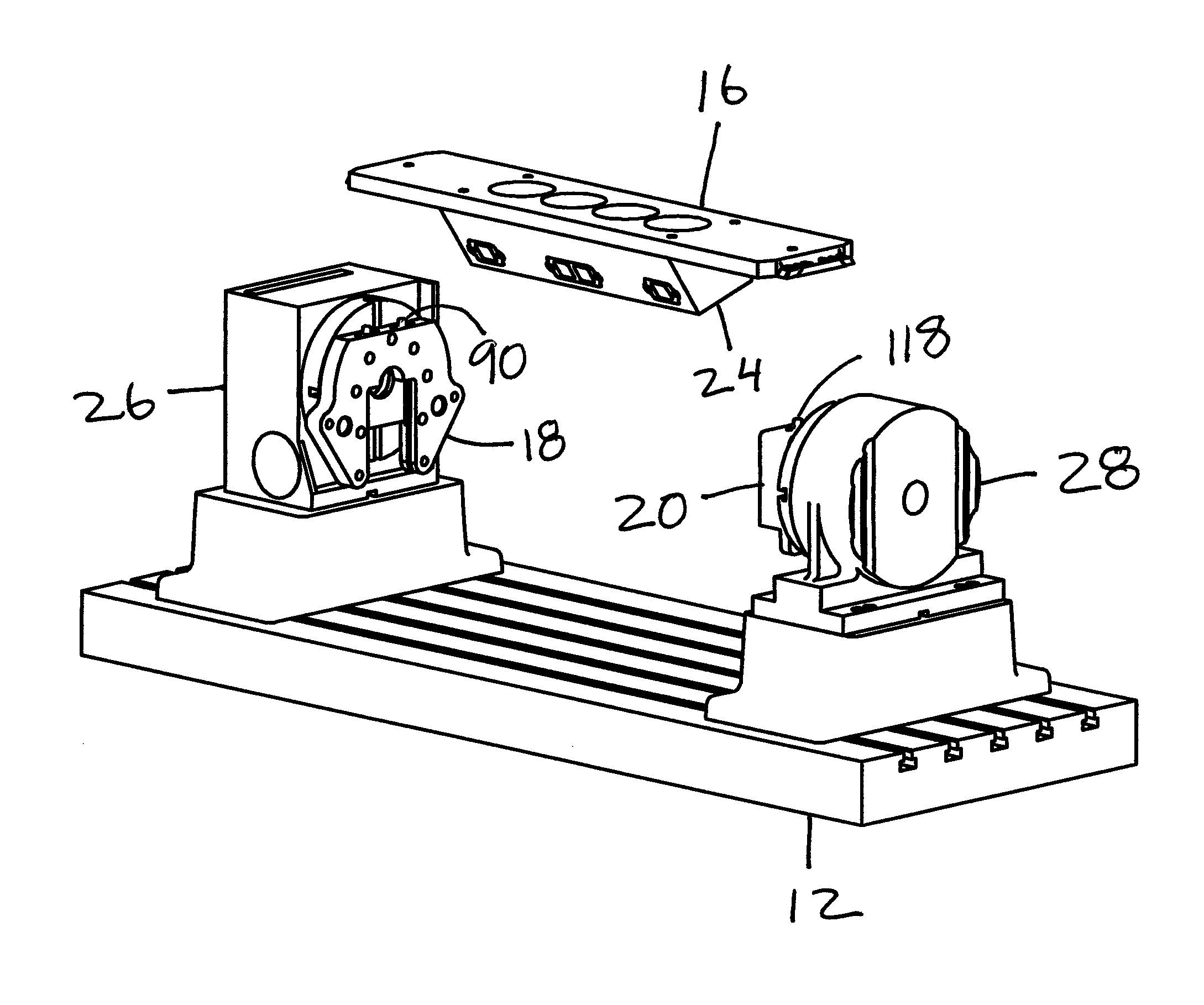
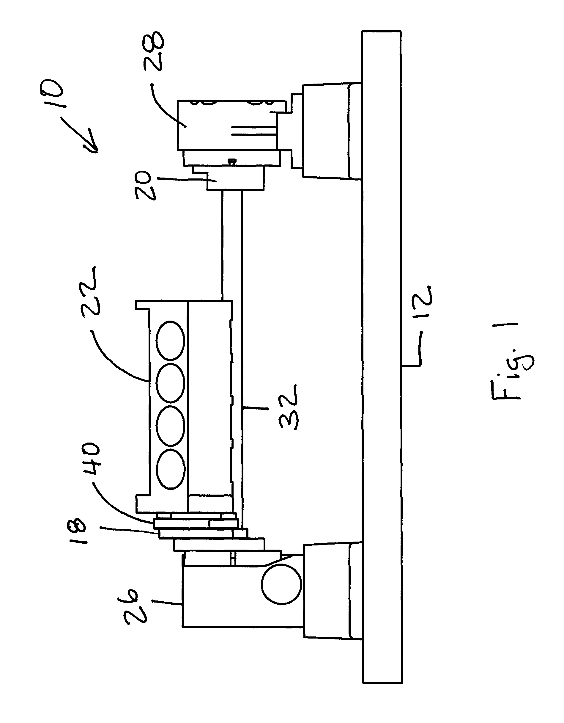
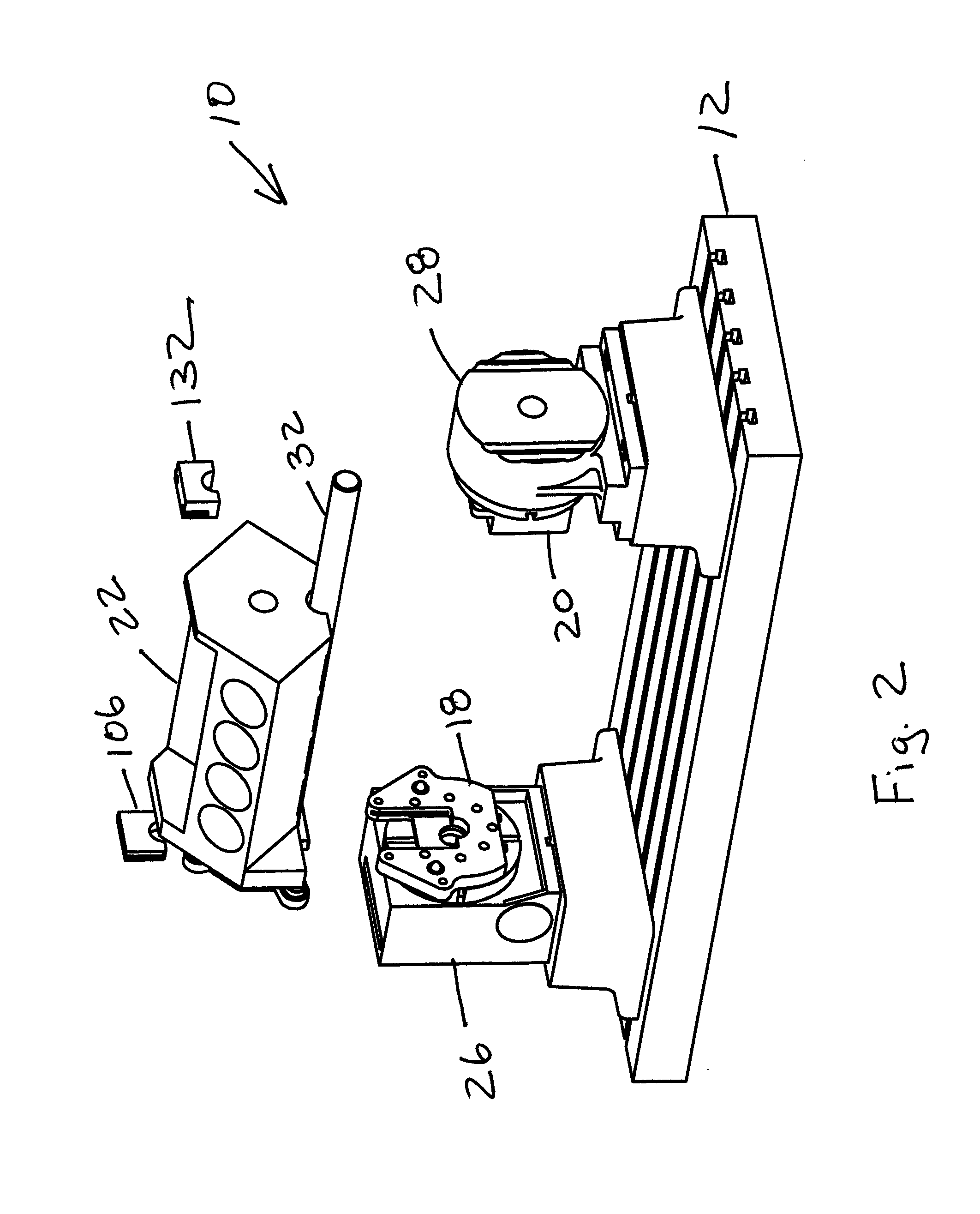
[0024]The present invention is a CNC fixture for quick change mounting of cylinder heads and engine blocks as work pieces during CNC machining operations. The CNC fixture 10 is shown in FIGS. 1-4. The CNC fixture 10 includes a base 12, a first sub fixture and second sub fixture attached to the base, block bar assembly 14, head plate 16, rotary plate 18 and tailstock plate 20. FIGS. 1-2 show the CNC fixture 10 with the block bar assembly 14 and FIGS. 3-4 shows the CNC fixture 10 with the head plate 16. The block bar assembly 14 is for mounting of the engine block 22. The head plate 16 is for mounting of the cylinder head 24. The base 12 is for mounting and supporting the CNC fixture 10 to a milling machine. The base 12 is usually a horizontal table of the milling machine. The first sub fixture is shown as a powered rotary table 26 attached to the base 12. The rotary table 26 is servo powered to be able to rotate and position the work piece thru 360 degrees of rotation about the axis ...


PUM


Abstract

A fixture for a milling machine to position and manipulate related work pieces. The fixture has a first sub fixture powered to rotate a rotary plate and a second sub fixture. The fixture includes one of a first plate fixture and a second plate fixture for the mounting of work pieces. The rotary plate is mounted to the first sub fixture such that the rotary plate can be rotated by the first sub fixture. The rotary plate attaches to one of the first plate fixture and the second plate fixture. The rotary plate includes a first precision surface adapted for mounting of the first plate fixture and a second precision surface adapted for mounting of the second plate fixture. The fixture includes a tailstock plate mounted to the second sub fixture. The tailstock plate attaches to one of the first plate fixture and the second plate fixture.

Description

[0001]This application claims the benefit of and incorporates by reference U.S. Provisional Application No. 61 / 680,060 filed Aug. 6, 2012BACKGROUND[0002]The present invention generally relates to computer controlled machining on computer controlled milling machines. More specifically, the present invention relates to a CNC fixture used with a computer controlled milling machine to hold and manipulate position of a work piece.[0003]The industry of milling out engine blocks and cylinder heads of fossil fuel engines is growing exponentially. This is due to the increase in demand of high performance engines. The demand for high performance engine also includes the demand for high precision. Currently, there are no CNC fixtures to keep up with the demand for the milling of matching engine blocks and cylinder heads quickly. Usually, the same milling machine is used to mill both the engine block and the matching cylinder head. That requires the install and removal of each the engine block ...

Claims


Application Information

Patent Timeline
Patent Type & Authority Patents(United States)
IPC IPC(8): B25B11/02B23C3/00B23Q3/06
CPCB23Q3/062B23C3/00B23Q3/061B25B11/02B23Q1/525
Inventor MCCULLOCH, JOSEPH W
Owner MCCULLOCH JOSEPH W
Why Eureka
Try Eureka