Emergency egress system for a construction machine

a construction machine and emergency exit technology, applied in the direction of steps, vehicle components, construction, etc., can solve the problems of increasing the risk of collision and/or damage with external objects, wall, doorway of a repair bay,

Active Publication Date: 2016-05-24
CATERPILLAR GLOBAL MINING HMS GMBH
View PDF14 Cites 4 Cited by
  • Summary
  • Abstract
  • Description
  • Claims
  • Application Information

AI Technical Summary

Benefits of technology

[0004]Various aspects of the present disclosure describe an emergency egress system for a construction machine. The emergency egress system includes a walkway platform in proximity of a cab. The walkway platform includes a first side attached to the construction machine and a second side opposed to the first side and distant from the cab. The emergency egress system includes an access panel assembly, a latch assembly, a handle assembly, a fixed ladder portion, and a slidable ladder portion. The access panel assembly is coupled to the walkway platform and includes a frame member and a door panel. The frame member is attached to the second side of the walkway platform. The door panel includes a first end and a second end. The first end is hinged to the frame member to allow for movement of the door panel between an open position and a closed position relative to the walkway platform. The second end is opposed to the first end and is structured to define a recess portion between the first side of the walkway platform and the door panel. The door panel includes a first surface directed towards an exit direction and a second surface proximal to the cab. The latch assembly is coupled to the second end of the door panel and to the first surface of the door panel. The latch assembly includes a first base member and a wing portion. The first base member is secured to the first surface of the door panel. The wing portion is attached to the first base member. The handle assembly is coupled to the second end of the door panel and the second surface of the door panel. The handle assembly includes a second base member and a holding portion. The second base member is secured to the second surface of the door panel such that the handle assembly works in conjunction with the latch assembly. The holding portion is attached to the first base member and is manipulable to rotate the latch assembly between a locked and an unlocked position. The fixed ladder portion includes a first end accommodated in the recess portion and is attached to the first side of the walkway platform in proximity to the cab. The slidable ladder portion includes a first end accommodated in the recess portion and is secured to the access panel assembly via the wing portion of the latch assembly, in the locked position. The holding portion is manipulable to rotate the latch assembly in the locked position to hold the fixed ladder portion and the slidable ladder portion together via the wing portion. This configuration facilitates the slidable ladder portion to be locked into the recess portion and maintains the door panel in the closed position. The holding portion is manipulable to rotate the latch assembly in the unlocked position to allow the wing portion to rotate. This configuration facilitates the slidable ladder portion to be unlocked for exit from the machine and for maintenance of the door panel in the open position.

Problems solved by technology

However, attachment of the emergency exit device to the exterior of the machine may alter an outer specification of the machine and insecurely expose the emergency exit device to an outside environment.
This may increase the risk of collision with and / or damage from external objects such as, a wall, doorway of a repair bay, and / or other components.
Accordingly, the emergency exit device may become damaged or deformed when operated in rough environments.

Method used


Image

  • Emergency egress system for a construction machine
  • Emergency egress system for a construction machine
  • Emergency egress system for a construction machine

Examples


Embodiment Construction

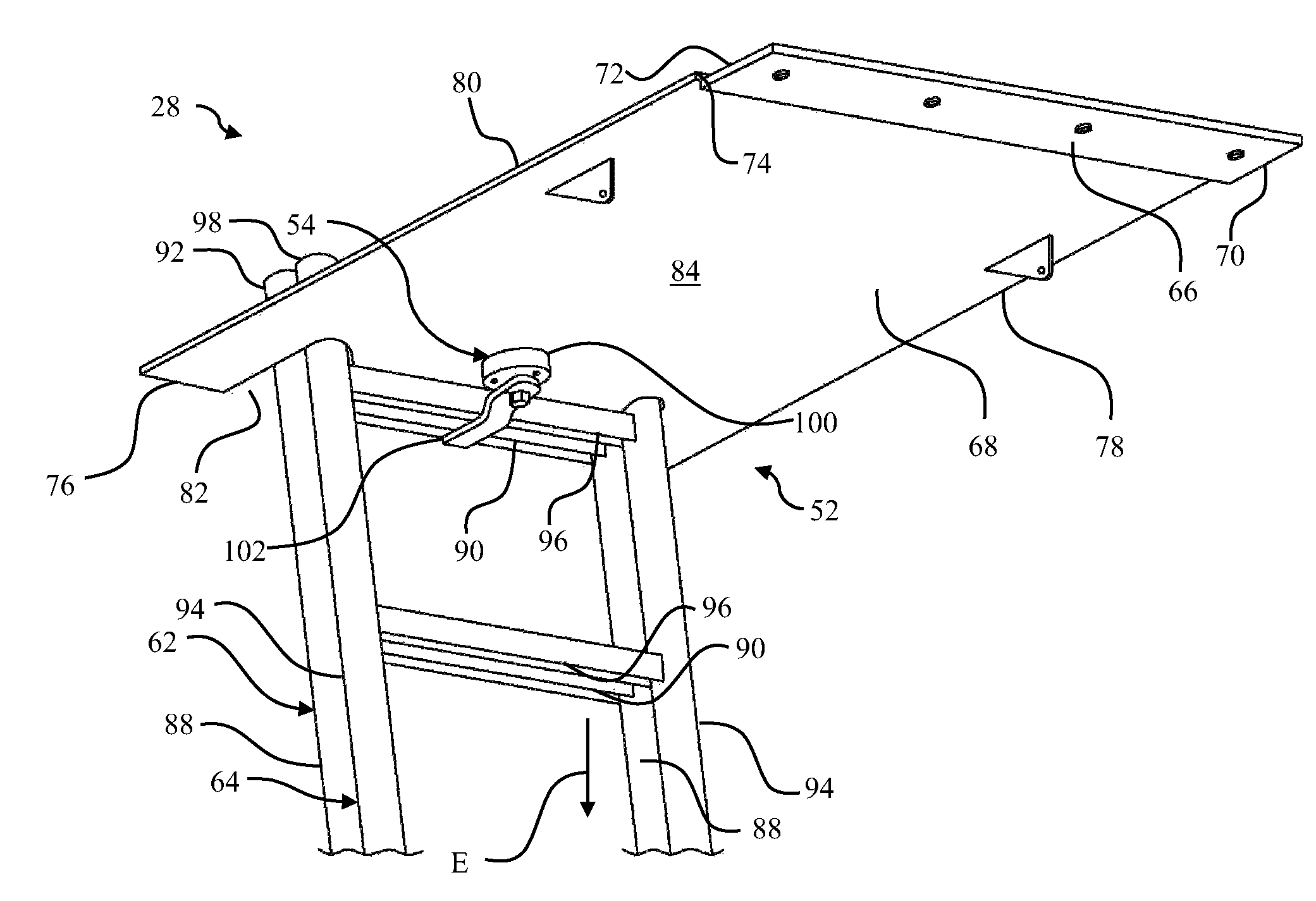
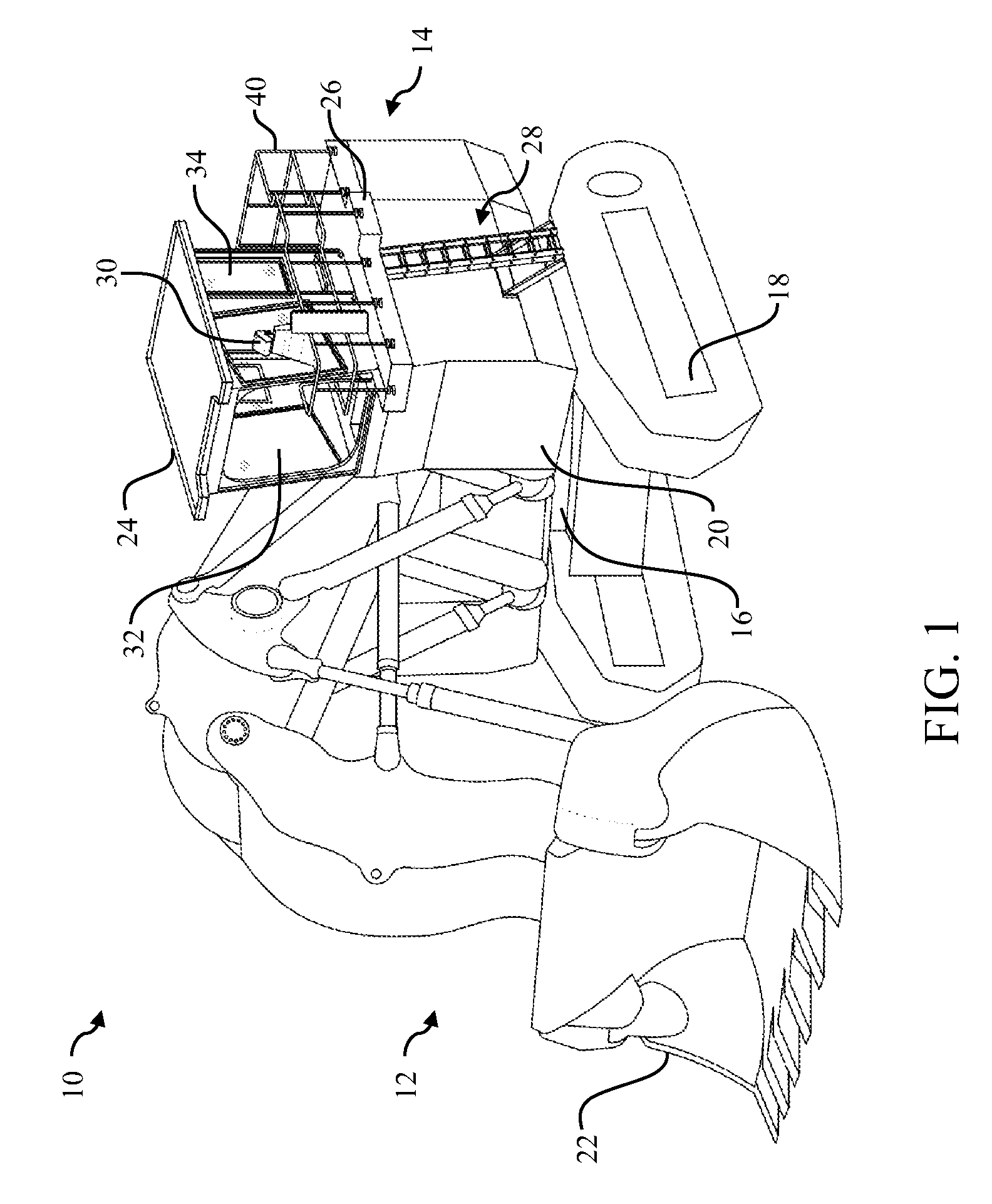
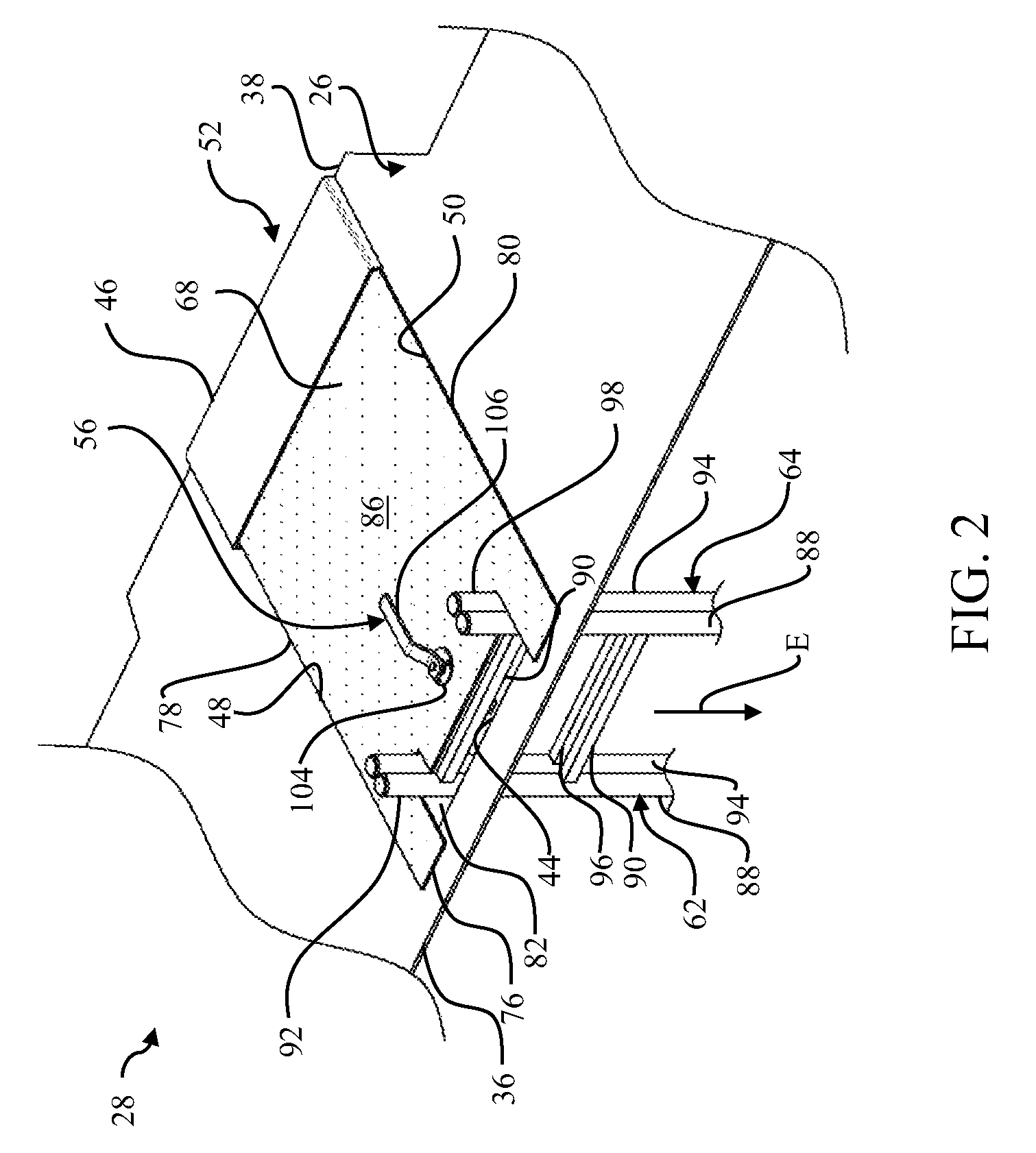
[0009]Referring to FIG. 1, there is shown a construction machine 10, which may be a moveable vehicle. The construction machine 10 includes a front end 12, a rear end 14, a frame 16, traction devices 18, a motor compartment 20, a work implement 22, a cab 24, a walkway platform 26, and an emergency egress system 28. The front end 12 includes the work implement 22. The rear end 14 includes the motor compartment 20, which may house a motor (not shown), a transmission, and / or other components (not shown) used to power the construction machine 10.

[0010]The frame 16 is attached to and supported on the one or more traction devices 18 in a manner known in the art. The frame 16 may embody a base that facilitates an operable connection between the one or more traction devices 18 and the motor (not shown). The traction devices 18 are powered and driven by the motor (not shown), to propel the construction machine 10 in a desired direction for operation. The motor (not shown) in the motor compart...


PUM


Abstract

An emergency egress system with an access panel assembly, a latch assembly, a handle assembly, a fixed ladder portion, and a slidable ladder portion, is disclosed. The access panel assembly includes a door panel. The latch assembly and the handle assembly are attached to the door panel. The handle assembly has a holding portion that works in conjunction with the latch assembly that has a wing portion. The holding portion is manipulable to rotate the latch assembly in the locked position to hold the fixed ladder portion and the slidable ladder portion together via the wing portion, which is to maintain the door panel in the closed position. The holding portion is manipulable to rotate the latch assembly to the unlocked position to allow the wing portion to rotate and release the slidable ladder portion for exit.

Description

TECHNICAL FIELD[0001]The present disclosure relates to personnel safety in construction machines. More particularly, the present disclosure relates to an emergency egress system, which includes a modular ladder arrangement that functions in conjunction with an associated access panel assembly.BACKGROUND[0002]Machines, such as vocational vehicles, off-highway haul trucks, motor graders, wheel loaders, and other types of large machines associated with construction, mining, and other industries, often include operator station that may be elevated relatively significantly above a ground. The machine may include platforms, stairs, and other support structures that permit an operator to move to various access points on the machine. Some of the access points are used for ingress to and egress from the machine. The operator station may be accessible via an entry position that may be relatively close to the ground. For example, the entry position may be linked to the operator station via a s...

Claims


Application Information

Patent Timeline
Patent Type & Authority Patents(United States)
IPC IPC(8): E02F9/08B60R3/02
CPCE02F9/0833B60R3/02
Inventor CAPRARO, SEBASTIAN
Owner CATERPILLAR GLOBAL MINING HMS GMBH
Why Eureka
Try Eureka