Heat exchange device

a heat exchange device and heat exchange technology, applied in the field of refrigeration, can solve the problems of high wind speed and small wind resistance, and achieve the effects of low wind speed, small wind resistance and large wind resistan

Active Publication Date: 2016-05-31
SANHUA(HANGZHOU) MICRO CHANNEL HEAT EXCHANGER CO LTD +1
View PDF20 Cites 2 Cited by
  • Summary
  • Abstract
  • Description
  • Claims
  • Application Information

AI Technical Summary

Benefits of technology

[0008]For a bent heat-exchange device, a distribution uniformity of wind speed across a surface of the heat-exchange device has significant influence on the heat-exchange performance of the heat-exchange device. For example, the heat-exchange device is disposed in a box, air flows from the bottom to the top, and the wind speed is not distributed uniformly across an entire surface of the heat-exchange device, which may influence the heat-exchange performance. In an embodiment, a bottom portion of the heat-exchange device is closer to the box such that the influence of the box on the wind is larger, the wind-resistance is large, and the wind speed is low. But, an upper portion of the heat-exchange device is farther from the box such that the influence of the box on the wind is smaller, the wind resistance is small, and the wind speed is high. As a result, the heat-exchange performance of the heat-exchange device is influenced. Therefore, the performance of the heat-exchange device may be improved by improving the distribution uniformity of the wind speed. Accordingly, the heat-exchange device of the invention improves the distribution uniformity of the wind speed to improve the heat-exchange performance.
[0009]With the substantially inverted V-shaped heat-exchange device according to embodiments of the invention, the wind-guide member may guide the wind toward the first and second heat exchangers, which may improve the distribution uniformity of the wind speed across the surface of the heat-exchange device to improve the performance of the heat-exchange device.

Problems solved by technology

For example, the heat-exchange device is disposed in a box, air flows from the bottom to the top, and the wind speed is not distributed uniformly across an entire surface of the heat-exchange device, which may influence the heat-exchange performance.
But, an upper portion of the heat-exchange device is farther from the box such that the influence of the box on the wind is smaller, the wind resistance is small, and the wind speed is high.

Method used


Image

  • Heat exchange device
  • Heat exchange device
  • Heat exchange device

Examples


Embodiment Construction

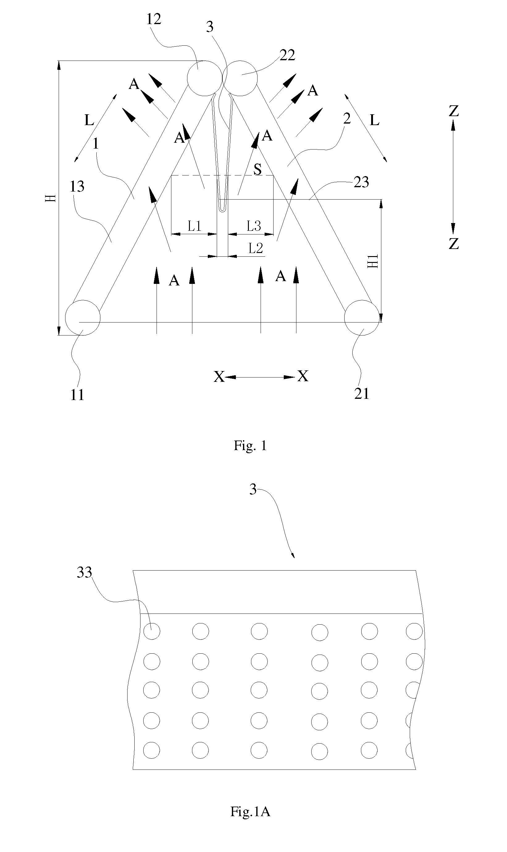
[0047]Distribution uniformity of wind speed across a surface of a heat-exchange device has significant influence on the heat-exchange performance of the heat-exchange device. FIG. 21 is a front view of a conventional heat-exchange device 100′ placed in a box 200′. As shown in FIG. 21, the conventional heat-exchange device 100′ has a substantially inverted V-shape, and wind blows from the bottom toward the top. The wind speed at a top portion of the conventional heat-exchange device 100′ is over-high, and there is a “dead region” at a lower portion of the conventional heat-exchange device 100′. In the “dead region,” the wind speed is low, and the heat-exchange efficiency is poor. Therefore, the wind speed is not distributed uniformly across a surface of the conventional heat-exchange device, which may disadvantageously influence the heat-exchange performance.

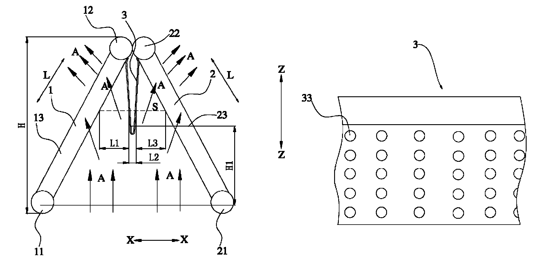
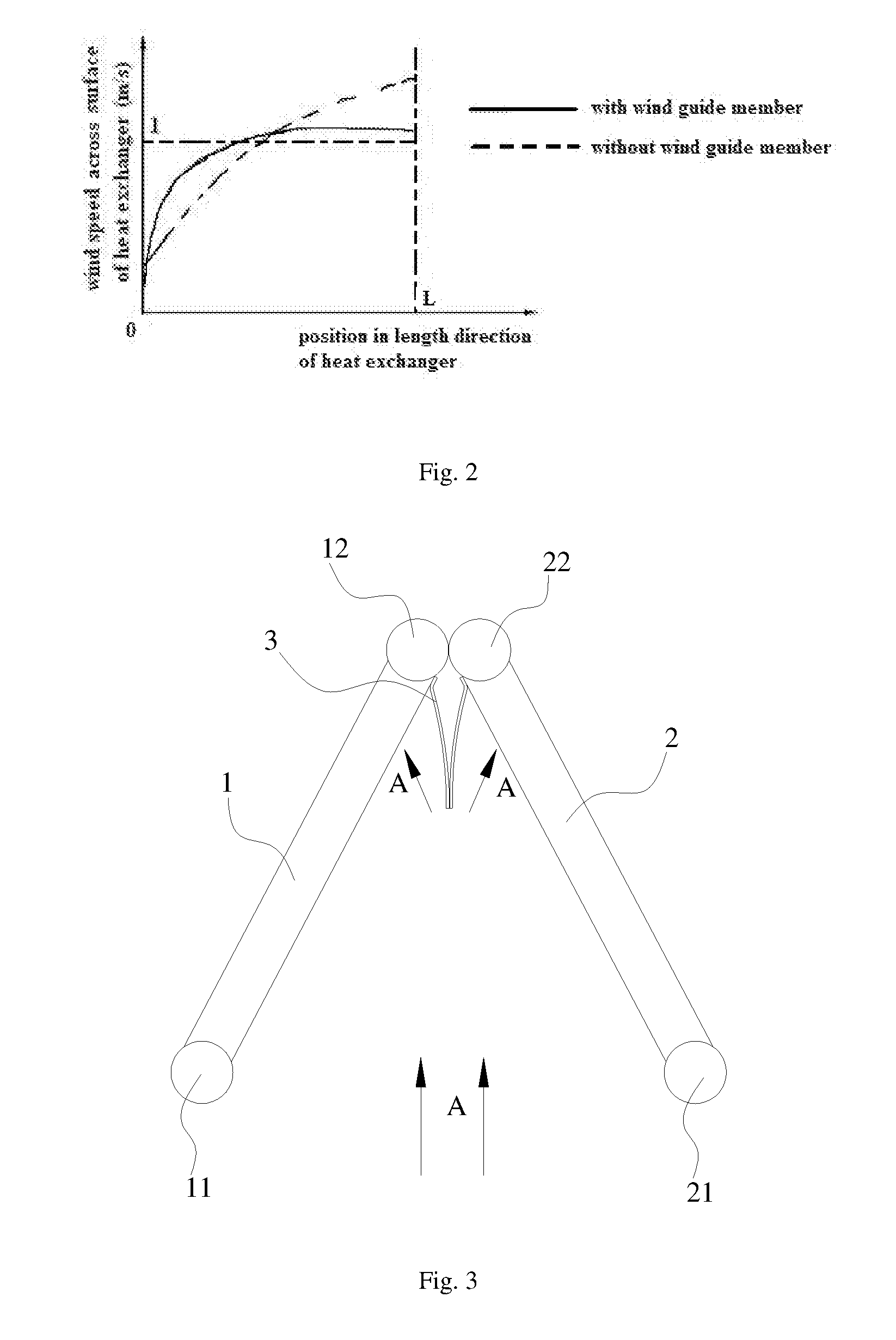
[0048]As shown in FIG. 1, a heat-exchange device according to embodiments of the invention comprises a first heat exchanger 1, ...


PUM


Abstract

A heat-exchange device comprises a first heat exchanger defining an upper end and a lower end. A second heat exchanger defines an upper end connected to the upper end of the first heat exchanger and a lower end spaced apart from the lower end of the first heat exchanger in a substantially longitudinal direction such that a predetermined angle between the first heat exchanger and second heat exchanger is between about 0 and 180°. A wind-guide member is disposed between the first heat exchanger and second heat exchanger for guiding wind toward the first heat exchanger and second heat exchanger.

Description

CROSS-REFERENCE TO RELATED APPLICATION[0001]This application claims priority to and benefit of the filing date of Chinese Patent Application 201110117006.3 filed on May 6, 2011 and entitled “Heat-exchange device,” which is hereby incorporated by reference in its entirety.BACKGROUND OF INVENTION[0002]1. Field of Invention[0003]The invention relates to, in general, refrigeration and, more particularly, a heat-exchange device.[0004]2. Description of Related Art[0005]A heat-exchange device may be used in wide application—for example, an air conditioner. A conventional heat-exchange device is generally flat-plate shaped. However, in some applications, the heat-exchange device needs to be bent to divide the heat-exchange device into a first heat-exchanger portion and a second heat-exchanger portion between which a predetermined angle is formed. In use, the heat-exchange device is placed in a box, and wind flows upward from a lower surface of the heat-exchange device and exchanges heat wit...

Claims


Application Information

Patent Timeline
Patent Type & Authority Patents(United States)
IPC IPC(8): F28F13/06F24F13/08F28D1/04F28B1/06F28F17/00F28F9/22
CPCF28F13/06F24F13/08F28D1/0426F28B1/06F28F17/005F28F2009/222F28D1/047F28D2001/0266
Inventor WANG, FENGJIANG, JIANLONGWU, XIAOHUIGAO, QIANGHUANG, LINJIE
Owner SANHUA(HANGZHOU) MICRO CHANNEL HEAT EXCHANGER CO LTD
Why Eureka
Try Eureka