Powder-filling system

a technology of filling system and powder, which is applied in the direction of magnetic bodies, packaging goods types, manufacturing tools, etc., can solve the problem that the opening size of the sieve needs to be much greater

Active Publication Date: 2016-07-05
DAIDO STEEL CO LTD
View PDF25 Cites 0 Cited by
  • Summary
  • Abstract
  • Description
  • Claims
  • Application Information

AI Technical Summary

Benefits of technology

[0034]With the powder-filling system according to the present invention, it is possible to fill a container with powder at an approximately uniform filling density.
[0035]With the sintered magnet production system according to the present invention using a powder-filling system according to the present invention, it is possible to obtain a sintered magnet having approximately homogeneous magnetic properties.

Problems solved by technology

If the powder particles are highly cohesive, the size of the openings of the sieve needs to be much greater than the powder particles, since the problem in this situation is to control the passage of aggregates of powder particles rather than individual powder particles.

Method used


Image

  • Powder-filling system
  • Powder-filling system
  • Powder-filling system

Examples


embodiment

(1) Embodiment of Powder-Filling System

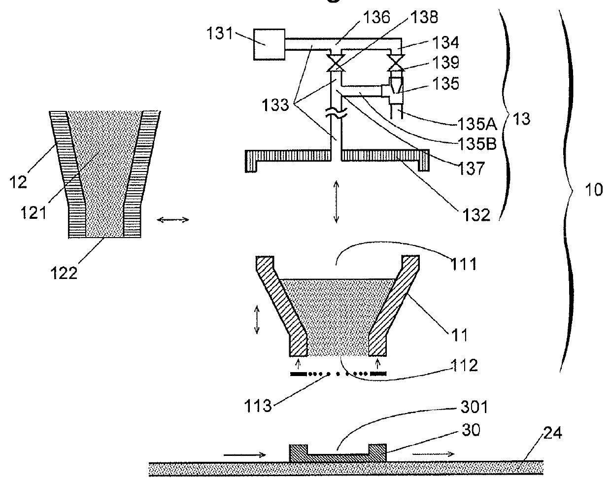
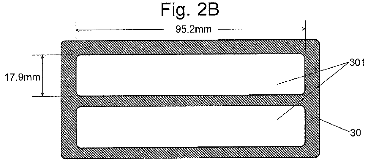
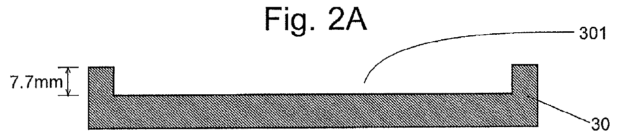
[0046]Initially, the powder-filling system 10 of the present embodiment is described. The powder-filling system 10 shown in FIG. 1 is intended to be used in a sintered magnet production system 20 of the present embodiment (which will be described later) to fill a container 30 with alloy powder to be used as the material of a sintered magnet, although it can also be used, without any change, to fill a container with any other type of powder. As shown in FIGS. 2A and 2B, the container 30 used in the present embodiment has two cavities 301 each of which has a roughly rectangular parallelepiped shape measuring 95.2 mm in length, 17.9 mm in width and 7.7 mm in depth and which are arranged side-by-side in their width direction.

(1-1) Configuration of Powder-Filling System 10

[0047]The powder-filling system 10 has a hopper 11, a powder supplier 12 for supplying alloy powder to the hopper 11, a gas supplier 13 for supplying compressed gas to the hopper 1...

first experiment

(3-1) First Experiment

[0080]In the first experiment, a sintered magnet was produced using the sieve member 113 and the container 30 (Present Example 1). Another sintered magnet was also produced using a sieve member having the same size of openings (8.6×2.2 mm) across the entire grid instead of the sieve member 113, and the container 30 (Comparative Example 1). In both Present Example 1 and Comparative Example 1, the obtained sintered magnets approximately measured 80 mm×15 mm×5 mm and were slightly smaller than the cavity 301 due to shrinkage which occurs during the sintering process. The sintered magnets obtained in Present Example 1 and Comparative Example 1 were each equally divided into six pieces along the length direction. Thus, six sintered-magnet pieces were obtained for each (FIG. 8A). For each of these sintered-magnet pieces, the residual magnetic flux density Br was measured. The result is shown in FIG. 8B.

[0081]In Comparative Example 1, the sintered-magnet pieces near t...

second experiment

(3-2) Second Experiment

[0084]In the second experiment, a sintered magnet was produced using the sieve member 1131 and the container 30A (Present Example 2). Another sintered magnet was also produced using a sieve member having the same size of openings (8.0×2.0 mm) across the entire sieve instead of the sieve member 1131, and the container 30A (Comparative Example 2). In both Present Example 2 and Comparative Example 2, twelve pieces of sintered magnets were obtained from the alloy powder placed in the twelve cavities of the container 30A. FIG. 9 shows the measured result of the residual magnetic flux density Br for each sintered magnet.

[0085]In Comparative Example 2, the distribution of the residual magnetic flux density Br was such that the sintered magnets produced from the alloy powder placed in the cavities corresponding to sieves A (FIG. 5C) had the highest residual magnetic flux densities Br, followed by sieves B, C (no difference could be recognized between B and C at the pr...


PUM

PropertyMeasurementUnit
widthaaaaaaaaaa
lengthaaaaaaaaaa
lengthaaaaaaaaaa

Abstract

A powder-filling system capable of filling a container with powder at an approximately uniform filling density has: a hopper having an opening removably and hermetically closably attached to the container, the hopper communicating with the container at the opening for supplying powder to a container; a powder supplier for supplying powder to the hopper; a gas supplier for repeatedly supplying compressed gas in a pulsed form to the hopper, with the hopper hermetically closably attached to the container; and a sieve member provided at the opening and having a smaller openings in a region near a side wall of the hopper than in its central region. The smaller openings in the region near the side wall of the hopper where the powder more easily falls from the hopper into the container impedes the fall of the powder in that region and improves the overall uniformity in the filling density.

Description

TECHNICAL FIELD[0001]The present invention relates to a powder-filling system for filling a container with powder.BACKGROUND ART[0002]When a compact is obtained from a powder material by compressing, sintering or other processes, a powder-filling system for putting powder into a container (shaping container) designed for molding (shaping) the powder is used. In such a powder-filling system, the container must be uniformly filled with powder at a predetermined density. Furthermore, in many cases, the filling density of the powder is required to be higher than the level achieved by simply pouring the powder into the container (this is called the “natural filling”). The operation of filling the container at a higher density than the density achieved by the natural filling is hereinafter called the “dense filling.”[0003]As one example of the system for the dense filling, Patent Literature 1 discloses a system which employs the air-tapping method to fill a container with powder. In this ...

Claims


Application Information

Patent Timeline
Patent Type & Authority Patents(United States)
IPC IPC(8): H01F41/02B65B1/04B65B1/16B22F3/00B30B15/30B65B7/28
CPCH01F41/0273B22F3/004B30B15/302B65B1/04B65B1/16B65B7/28H01F41/0266B22F3/10H01F1/0571H01F1/0577
Inventor SAGAWA, MASATOITATANI, OSAMUYOSHIKAWA, NORIO
Owner DAIDO STEEL CO LTD
Why Eureka
Try Eureka