Fluid flow control device for a container

a flow control device and container technology, applied in the direction of liquid handling, sealing, caps, etc., can solve the problems of long standing unresolved disadvantages of conventional lids for containers, no control over the flow of fluid through the aperture, and substantial lids

Inactive Publication Date: 2016-07-19
LIDS2GO HLDG
View PDF37 Cites 6 Cited by
  • Summary
  • Abstract
  • Description
  • Claims
  • Application Information

AI Technical Summary

Problems solved by technology

However, there remain long standing unresolved disadvantages associated with conventional lids for containers.
One disadvantage of conventional lids for container may be that for each configuration of container there is a specific configuration of lid.
Another disadvantage of conventional lids for containers can be that the lid has one or more apertures which allow the fluid to flow from the container regardless of the orientation of the container.
For example, unless the apertures of a conventional lid are plugged, there is no control over the flow of fluid through the aperture.
Another disadvantage of conventional lids which insert inside of containers can be that the lids are substantially planar and the lid edges to not sufficiently seal in contact with the interior wall of the container.
Additionally, apertures formed by combination of the interior wall and the lid may not be adjustable in dimension relations by adjustment of the lid in relation to the interior wall of the container.

Method used


Image

  • Fluid flow control device for a container
  • Fluid flow control device for a container
  • Fluid flow control device for a container

Examples


Embodiment Construction

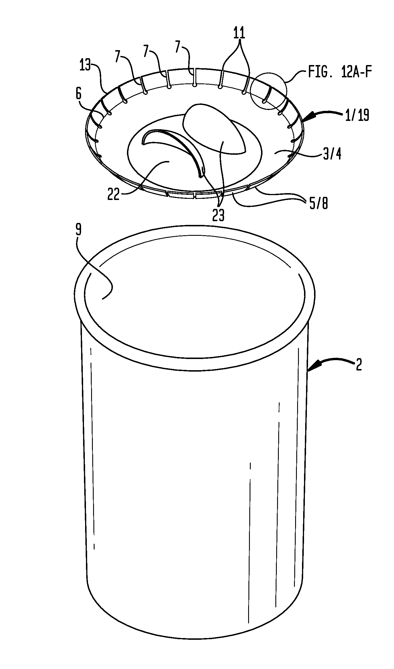
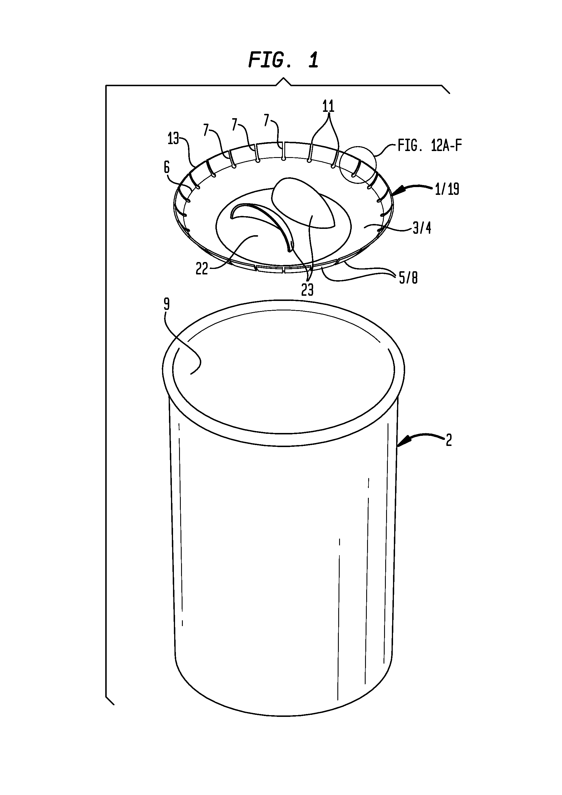
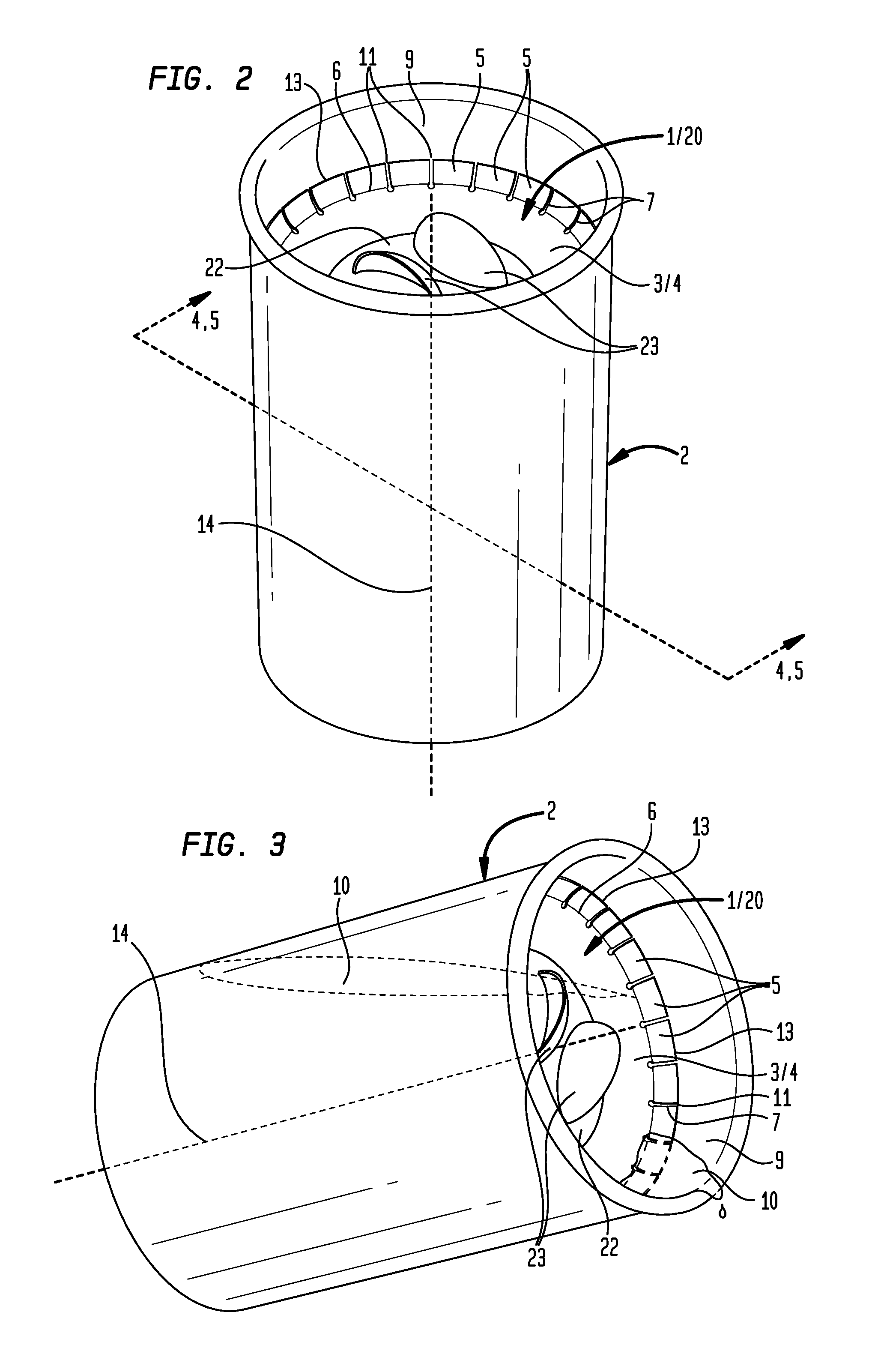
[0038]Now referring primarily to FIGS. 1 through 3, which illustrate a method of using a particular embodiment of a fluid flow control device (1). The fluid flow control device (1) can be utilized in combination with a container (2). The particular embodiment of the fluid flow control device (1) shown in the examples of FIGS. 1 through 3 includes a solid body (3) having a concave surface (4). A plurality of flexible fluid flow control elements (5) coupled in spaced apart relation about the peripheral edge (6) of the solid body (3) define a corresponding plurality of radial slit elements (7) between each adjacent pair of the plurality of flexible fluid flow control elements (5)(as shown in the example of FIG. 1), and as further described in detail below.

[0039]An amount of fluid (10)(shown in broken line in the example of FIG. 3) can be transferred to a container (2). A user can locate the fluid flow control device (1) inside the container (2) by contacting the outwardly disposed curv...


PUM


Abstract

A fluid flow control device having plurality of flexible fluid flow control elements disposed in spaced apart relation about the periphery of a solid body which insertably secured in a container provides a plurality of apertures in spaced apart relation about the periphery of the solid body which control the flow rate of an amount of fluid from the container.

Description

[0001]This application is the United States National Stage of International Patent Cooperation Treaty Application No. PCT / US2012 / 000081, filed Feb. 10, 2012, which claims the benefit of U.S. Provisional Patent Application No. 61 / 441,417, filed Feb. 10, 2011, each hereby incorporated by reference herein.I. TECHNICAL FIELD[0002]Generally, a fluid flow control device having a plurality of flexible fluid flow control elements disposed in spaced apart relation about the periphery of a solid body which insertably secured in a container provides a plurality of apertures in spaced apart relation about the periphery of the solid body which control the flow rate of an amount of fluid from the container.II. BACKGROUND[0003]There a numerous and wide variety of conventional lids which couple to containers for the purpose of regulating flow of fluids from the containers. However, there remain long standing unresolved disadvantages associated with conventional lids for containers.[0004]One disadva...

Claims


Application Information

Patent Timeline
Patent Type & Authority Patents(United States)
IPC IPC(8): B65D47/12B65D39/02A47G19/22
CPCB65D39/02B65D47/12A47G19/2211
Inventor PHILLIPS, SHANDLEY K.PHILLIPS, ALLYSON L.
Owner LIDS2GO HLDG
Why Eureka
Try Eureka