Control system for an irrigation system

a control system and irrigation system technology, applied in the direction of computer control, process and machine control, instruments, etc., can solve the problems of inconvenient control, inconvenient control, tedious manual control, etc., and achieve the effect of quick and easy creation of new, quick and easy creation and/or modification

Inactive Publication Date: 2016-08-09
LINDSAY CORP
View PDF14 Cites 9 Cited by
  • Summary
  • Abstract
  • Description
  • Claims
  • Application Information

AI Technical Summary

Benefits of technology

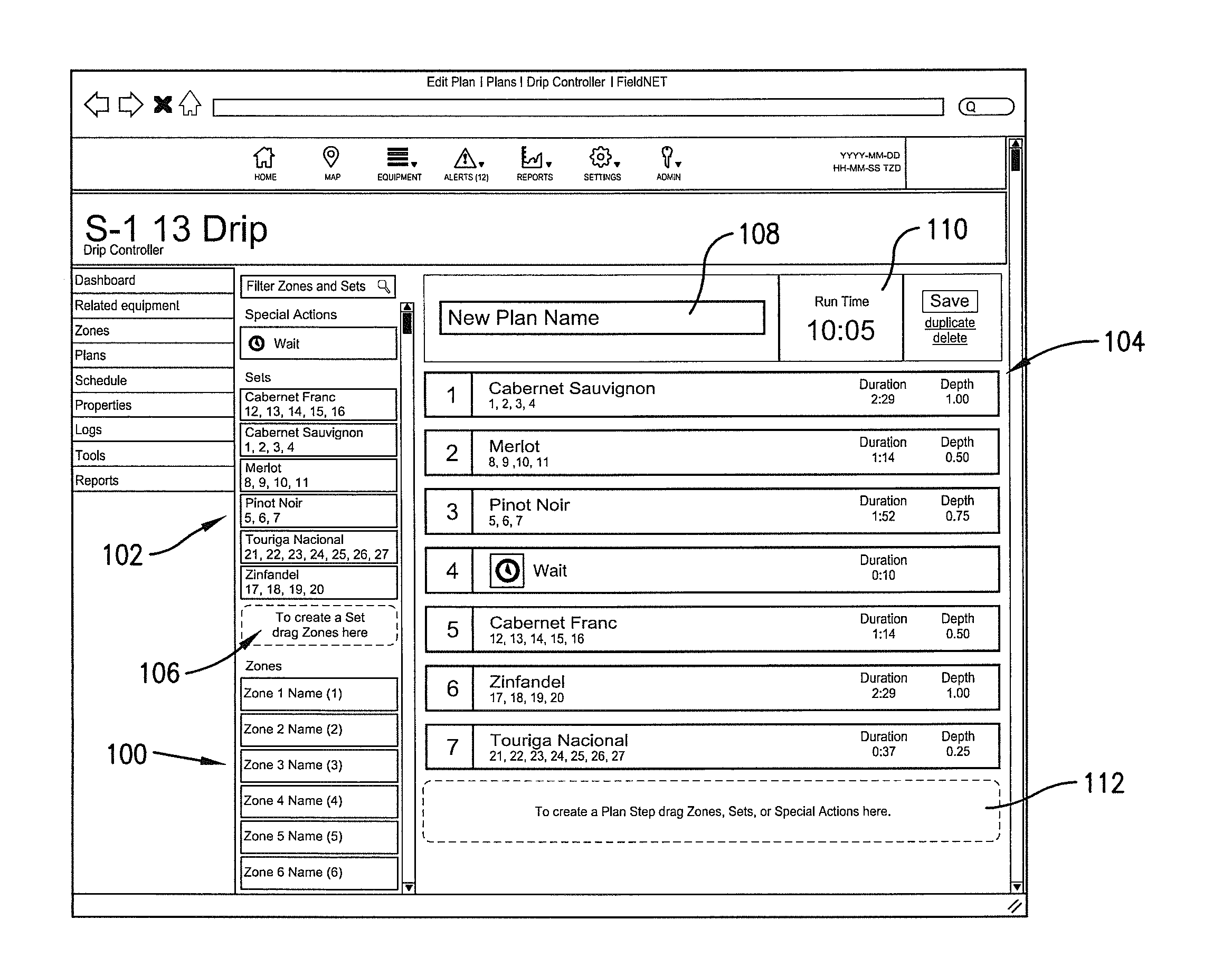
[0009]The graphical user interface greatly simplifies the creation, modification, and / or implementation of the irrigation plans. In accordance with one aspect of the invention, the graphical user interface has an irrigation plan editing page that displays an irrigation zone list, an irrigation set list, and an irrigation plan field. The irrigation zone list contains a listing of irrigation zones of the low-volume irrigation system, with each of the zones being controlled by at least one of the valve controllers. For example, if the low-volume irrigation system has four valves and therefore four irrigation zones, the irrigation zone list may include four zone listings, one for each irrigation zone. The information in the zone list may be obtained from the irrigation system controller or may be entered by a user.
[0012]In accordance with another important aspect of the invention, the user interface includes functionality that permits an irrigation zone listing from the irrigation zone list to be copied into any of the irrigation set listings. For example, using the four zone irrigation system mentioned above, a user may click-on or otherwise select the zone listing for irrigation zone 1 and drag and drop it into an existing irrigation set or a new irrigation set. This allows a user to quickly and easily create new and / or modify existing irrigation sets from the irrigation zone listings. In alternate embodiments, other user interface methods of copying information may be used instead of drag and drop functionality.
[0013]Similarly, the functionality permits an irrigation zone listing from the irrigation zone list or an irrigation set listing from the irrigation set list to be dragged and dropped or otherwise copied into a new or existing irrigation plan to create or modify irrigation steps within the irrigation plan. For example, a user may click-on or otherwise select a second irrigation set listing and drop it into the irrigation plan to become the first step of the plan, click-on or otherwise select zone listing 1 and drop it into the irrigation plan to become the second step of the plan, and then click-on or otherwise select a wait period and drop it into the irrigation plan to become the third step of the plan. This allows a user to quickly and easily create and / or modify an irrigation plan from existing irrigation zone listings and irrigation set listings. In alternate embodiments, other user interface methods of copying information may be used instead of the drag and drop functionality.

Problems solved by technology

Unfortunately, with increased irrigation by more and more growers, the amount of water available for irrigation is sometimes limited, especially in drought years when it is most crucial.
As a result, water sources in many areas are becoming more tightly regulated and restricted.
Such manual control is tedious, time consuming, and imprecise.
Unfortunately, existing control systems require knowledge of confusing and non-intuitive programming and / or controls.
Moreover, most known control systems can only be set-up and adjusted at the controller itself, which is typically mounted in a panel near other components of the low-volume irrigation system.
Some control systems have remotely accessible user interfaces, but such interfaces typically just mirror the local interfaces and are therefore just as confusing and non-intuitive.
Similar problems exist for control systems designed for center pivot irrigation systems, lateral move irrigation systems, and other types of irrigation systems.

Method used


Image

  • Control system for an irrigation system
  • Control system for an irrigation system
  • Control system for an irrigation system

Examples


Embodiment Construction

[0040]The following detailed description references the accompanying drawing figures that illustrate specific embodiments in which the invention may be practiced. The embodiments are intended to describe aspects of the invention in sufficient detail to enable those skilled in the art to practice the invention. Other embodiments can be utilized and changes can be made without departing from the scope of the invention. The following detailed description is, therefore, not to be taken in a limiting sense. The scope of the invention is defined only by the appended claims, along with the full scope of equivalents to which such claims are entitled.

[0041]In this description, references to “one embodiment”, “an embodiment”, or “embodiments” mean that the feature or features being referred to are included in at least one embodiment of the technology. Separate references to “one embodiment”, “an embodiment”, or “embodiments” in this description do not necessarily refer to the same embodiment ...


PUM


Abstract

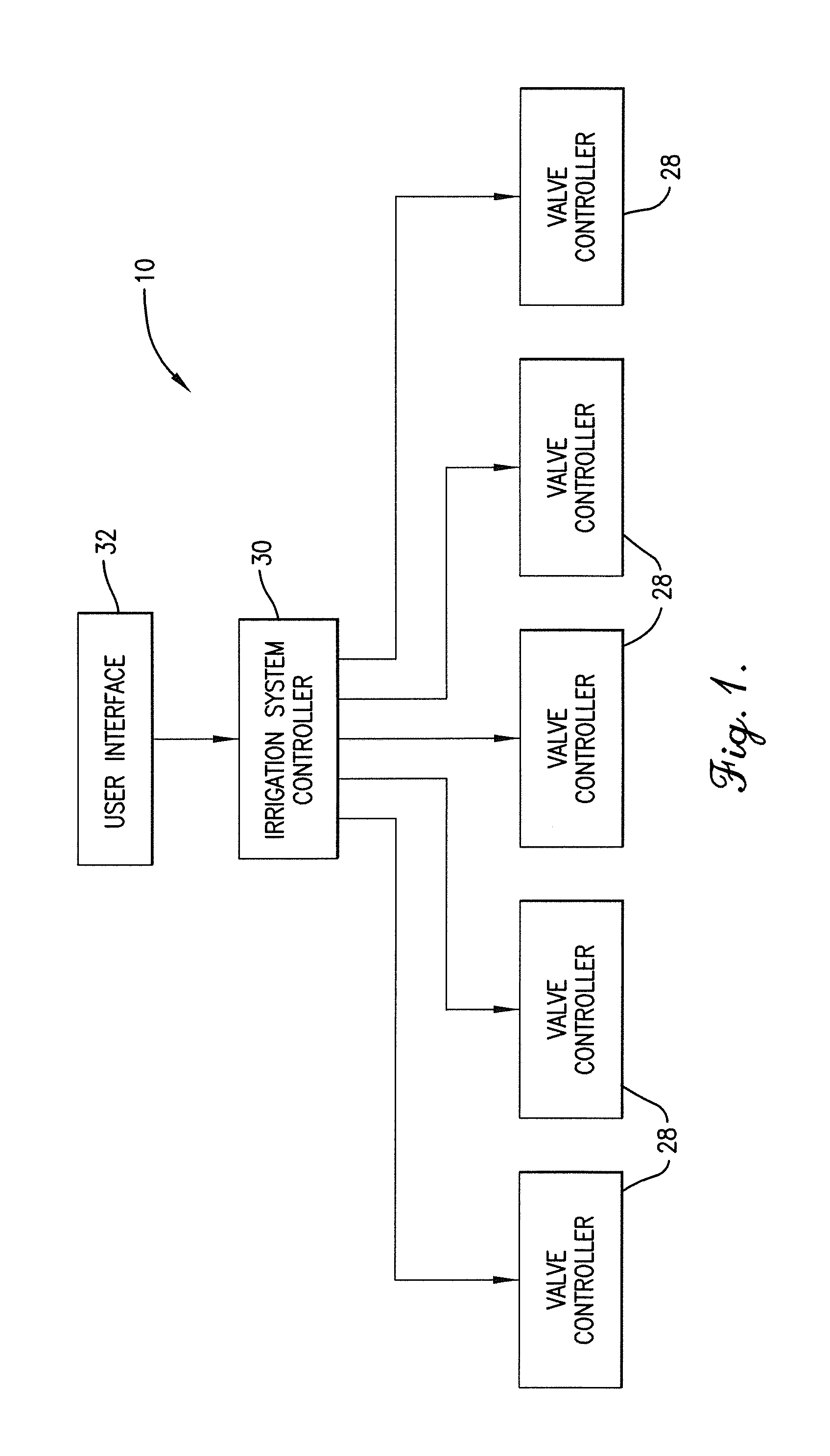
A control system for a low-volume irrigation system includes a plurality of valve controllers for opening and closing valves; an irrigation system controller for controlling the valve controllers in accordance with an irrigation plan; and a graphical user interface for allowing a user to interact with the irrigation controller and to create the irrigation plan. The graphical user interface displays an irrigation zone list, an irrigation set list, and an irrigation plan field. The user interface has drag and drop functionality that permits an irrigation zone listing from the irrigation zone list to be dragged and dropped into any of the irrigation set listings in the irrigation set list and that permits an irrigation zone listing or an irrigation set listing to be dragged and dropped into the irrigation plan to create irrigation steps within the irrigation plan.

Description

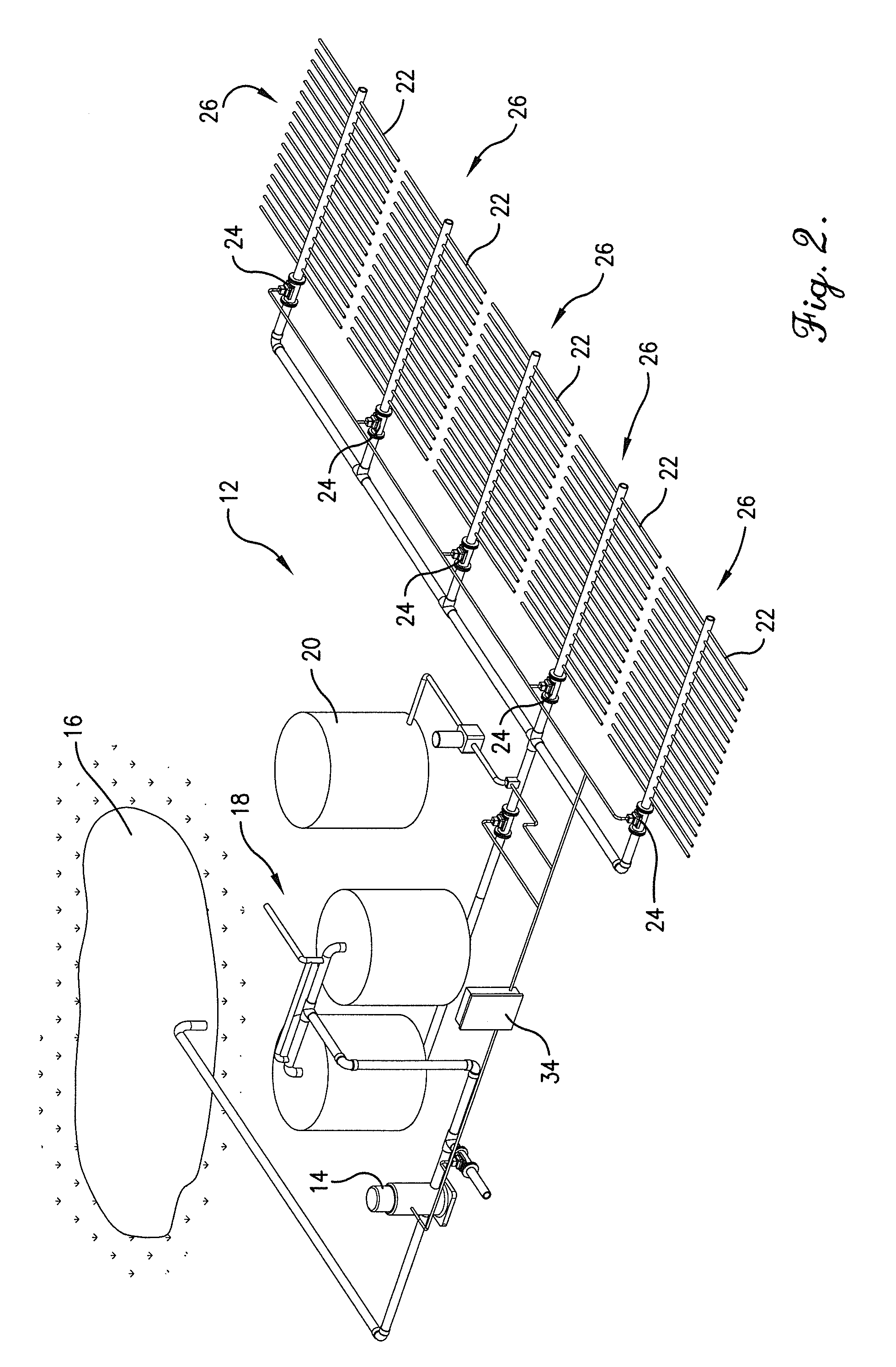
BACKGROUND[0001]1. Field[0002]Embodiments of the present invention relate to control systems for irrigation systems. More particularly, embodiments of the invention relate to a graphical user interface that allows users to more quickly and intuitively create and manage irrigation plans for an irrigation system.[0003]2. Related Art[0004]Mechanized irrigation systems are frequently used for irrigating crops and other plants. Unfortunately, with increased irrigation by more and more growers, the amount of water available for irrigation is sometimes limited, especially in drought years when it is most crucial. As a result, water sources in many areas are becoming more tightly regulated and restricted.[0005]Low volume irrigation, also known as drip irrigation, trickle irrigation, micro irrigation, and / or localized irrigation, is an irrigation method that saves water and fertilizer by allowing water to drip or otherwise be delivered slowly to the roots of plants, either onto the soil surf...

Claims


Application Information

Patent Timeline
Patent Type & Authority Patents(United States)
IPC IPC(8): A01G25/16
CPCA01G25/16A01G25/165G05B15/02G06F3/0484A01G25/162Y02A40/22
Inventor NEESEN, WARD V.ANDREWS, REECE R.BURKEY, BRANT
Owner LINDSAY CORP
Why Eureka
Try Eureka