
Connector assembly with automatic secondary lock

a secondary locking and connector technology, applied in the direction of coupling device connection, pedestrian/occupant safety arrangement, vehicular safety arrangement, etc., can solve the problems of unintentional removal and inhibit the placement of the secondary locking member in a half-fitting position, and achieve the effect of no tension or stress on the components

Active Publication Date: 2016-08-09
APTIV TECH LTD
View PDF26 Cites 12 Cited by
  • Summary
  • Abstract
  • Description
  • Claims
  • Application Information

AI Technical Summary

Benefits of technology

[0007]According to one aspect of the invention, a connector assembly is provided comprising a connector housing, a secondary locking member and a spring, whereby the secondary locking member and the spring are assigned to the connector housing. The secondary locking member is movable between a first and a second position and when placed in its second position, it serves to secure the mating of the connector housing in the case that the connector housing is mated to a corresponding counter-connector. The second position is thus the locking position of the secondary locking member. During mating, the spring is biased to cause the secondary lock to move automatically into a locked position when the connector assembly is fully mated with is corresponding counter-connector without need for an operator to push the secondary locking member into the locked position. The spring is biased to cause the connector housing and its corresponding counter-connector to spring back to an open position if the two connectors are not fully mated. In an exemplary embodiment, there is no tension or stress on components when the connectors are in the mated or unmated conditions. With the feature that the spring is adapted “to bias” the secondary locking member into its second position it is herein meant, that the spring is arranged such that upon mating of connector housing with a corresponding counter-connector the spring will automatically move or dispose the secondary lock into its second position.

Problems solved by technology

However, in the case described in the WO'623, it is possible to place the secondary locking member in a half-fitting position, in which it may not function properly and in which it is not fixed to the connector, and therefore can be removed unintentionally.
As long as the secondary locking member is not placed in this locking position, the spring arms are biased against the edges of the inclined channel, and due to the resulting restoring spring force they inhibit the secondary locking member to be placed in a half-fitting position unintentionally: i.e. the spring force causes the secondary locking member to move back into its pre-locked position.

Method used


Image

  • Connector assembly with automatic secondary lock
  • Connector assembly with automatic secondary lock
  • Connector assembly with automatic secondary lock

Examples


Embodiment Construction

[0021]In one aspect, the present invention improves the state of the art by providing a connector assembly with an improved secondary locking mechanism. In another aspect, the present invention further improves the state of the art by providing a novel approach for performing electrical monitoring for determining whether an electrical connector is mated with a corresponding mating connector.

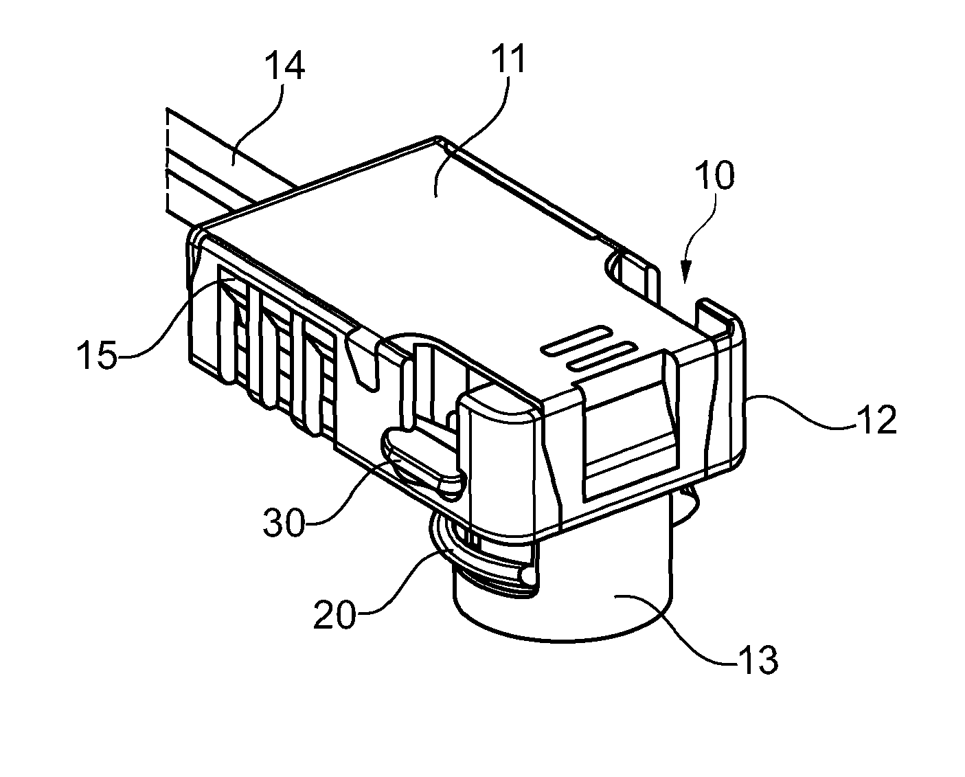
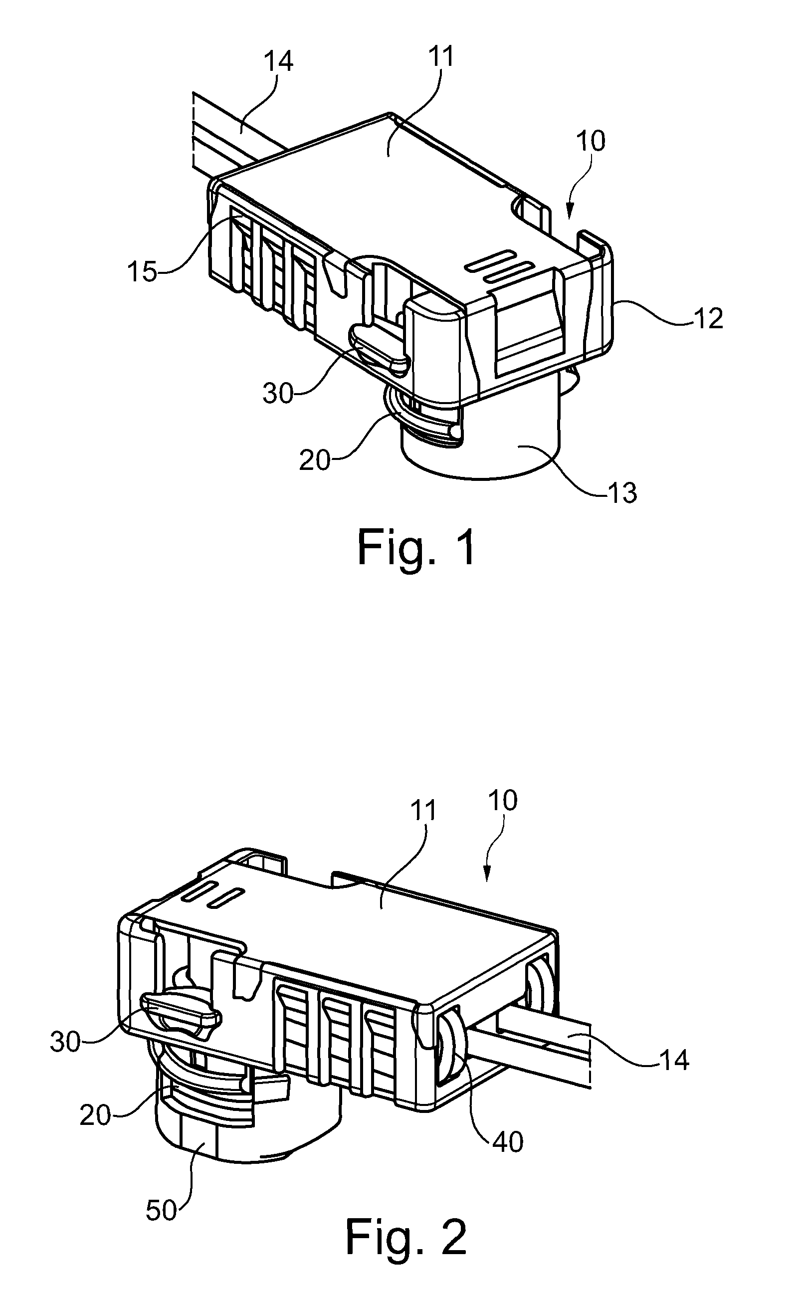
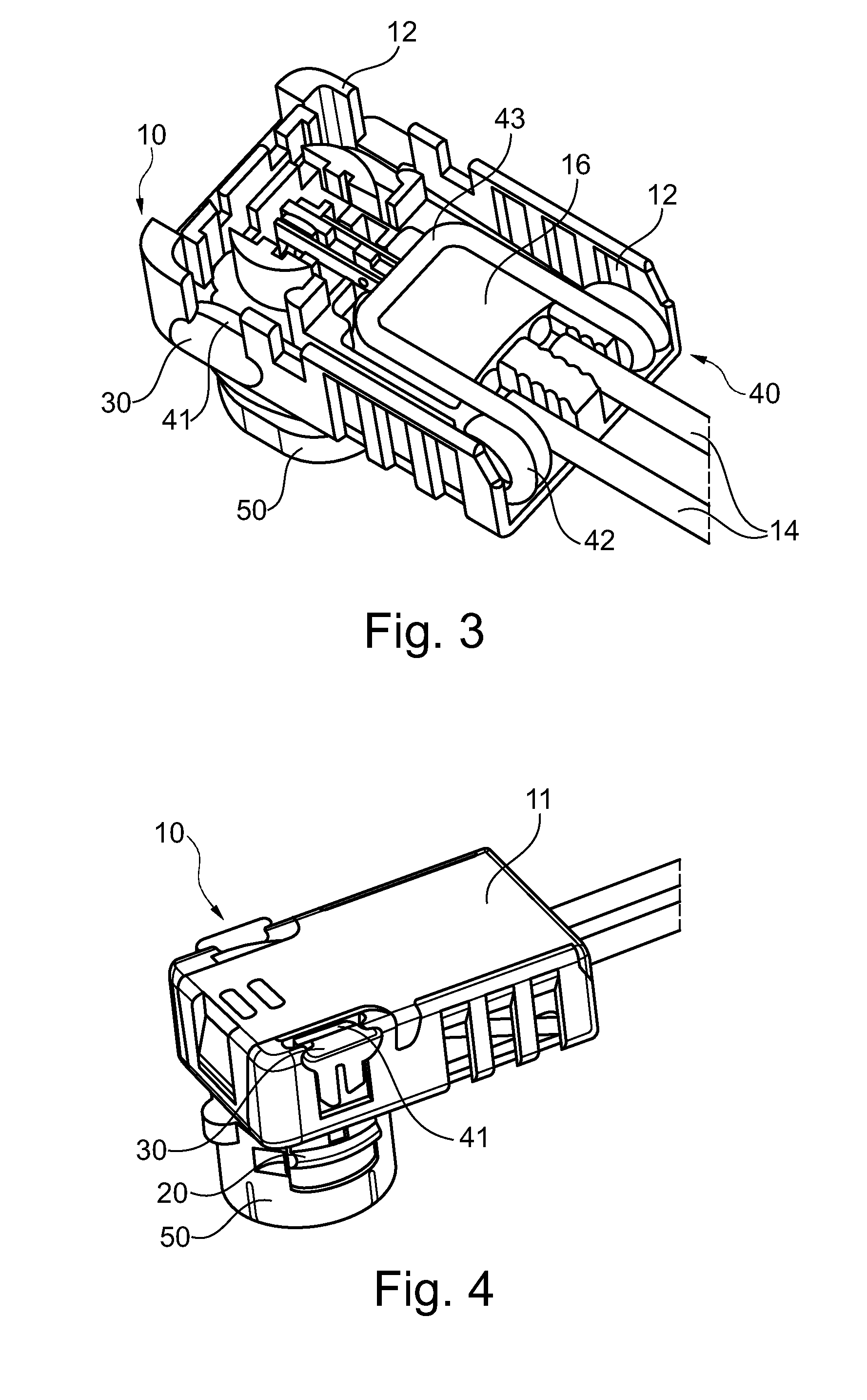
[0022]FIG. 1 shows a perspective, three-dimensional view of a connector housing 10 in accordance with the invention. The connector housing 10 comprises a main body 12 and a cover 11 which is removably latched to the main body 12 by means of latch connections 15. At the bottom side of the main body 12 a cylindrical plugging portion 13 is provided. The skilled person will recognize, that the plugging portion 13 is adapted to co-operate with typical airbag squib sockets and that the device shown is thus an airbag squib connector. On opposite sides of the plugging portion 13, two latching arms 20 are...


PUM


Abstract

The present invention relates to a connector assembly in particular for airbag connection systems, including a connector housing and a secondary lock. The housing is further provided with a spring, such that the secondary lock is movable between a first and a second position and the spring forces the secondary lock into its second position when the connector housing is fully mated with a corresponding mating connector.

Description

CROSS-REFERENCE TO RELATED APPLICATION[0001]This application is a national stage application under 35 U.S.C. §371 of PCT Application Number PCT / EP2013 / 055480 having an international filing date of 15 Mar. 2013, which designated the United States, said PCT application claiming the benefit of priority under Article 8 of the Patent Cooperation Treaty to U.S. Patent Application No. 61 / 725,234, having filing date of Nov. 12, 2012, the entire disclosure of each of which are hereby incorporated herein by reference.TECHNICAL FIELD OF THE INVENTION[0002]The present invention relates to a connector assembly comprising a secondary locking member and a spring which biases, i.e. automatically disposes, the secondary locking member into a locked position when the connector assembly is fully mated with a corresponding mating connector.BACKGROUND OF THE INVENTION[0003]In many applications, the safe coupling of connectors is of high importance. For example, in the case of car safety systems, as e.g....

Claims


Application Information

Patent Timeline
Patent Type & Authority Patents(United States)
IPC IPC(8): B60R21/01B60R21/20B60R21/16H01R13/627H01R13/639H01R13/70
CPCB60R21/16B60R21/20H01R13/627H01R13/70H01R13/6273H01R13/639B60R2021/01006H01R13/701H01R13/713H01R2201/26
Inventor GUNREBEN, MICHAELREGNIER, VINCENT
Owner APTIV TECH LTD
Learn More