

Vehicular cowl structure
a cowl and cowl brace technology, applied in the direction of superstructure subunits, vehicle components, pedestrian/occupant safety arrangements, etc., can solve the problems that the cowl inner panel and the cowl brace may interfere with each other, and achieve the effect of effective restraint or prevention and improving nv performan
- Summary
- Abstract
- Description
- Claims
- Application Information
AI Technical Summary
Benefits of technology
Problems solved by technology
Method used
Image

Examples
first embodiment
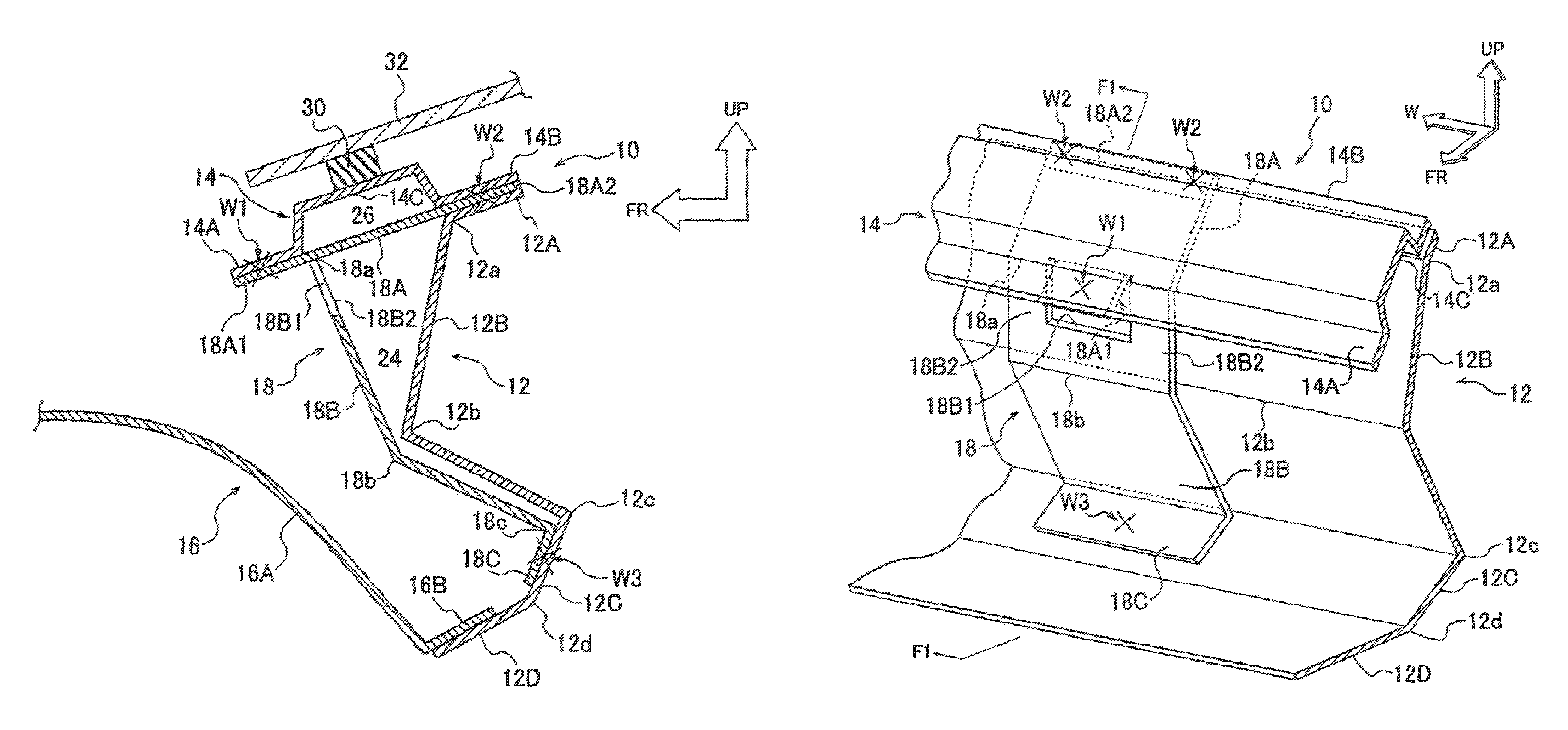
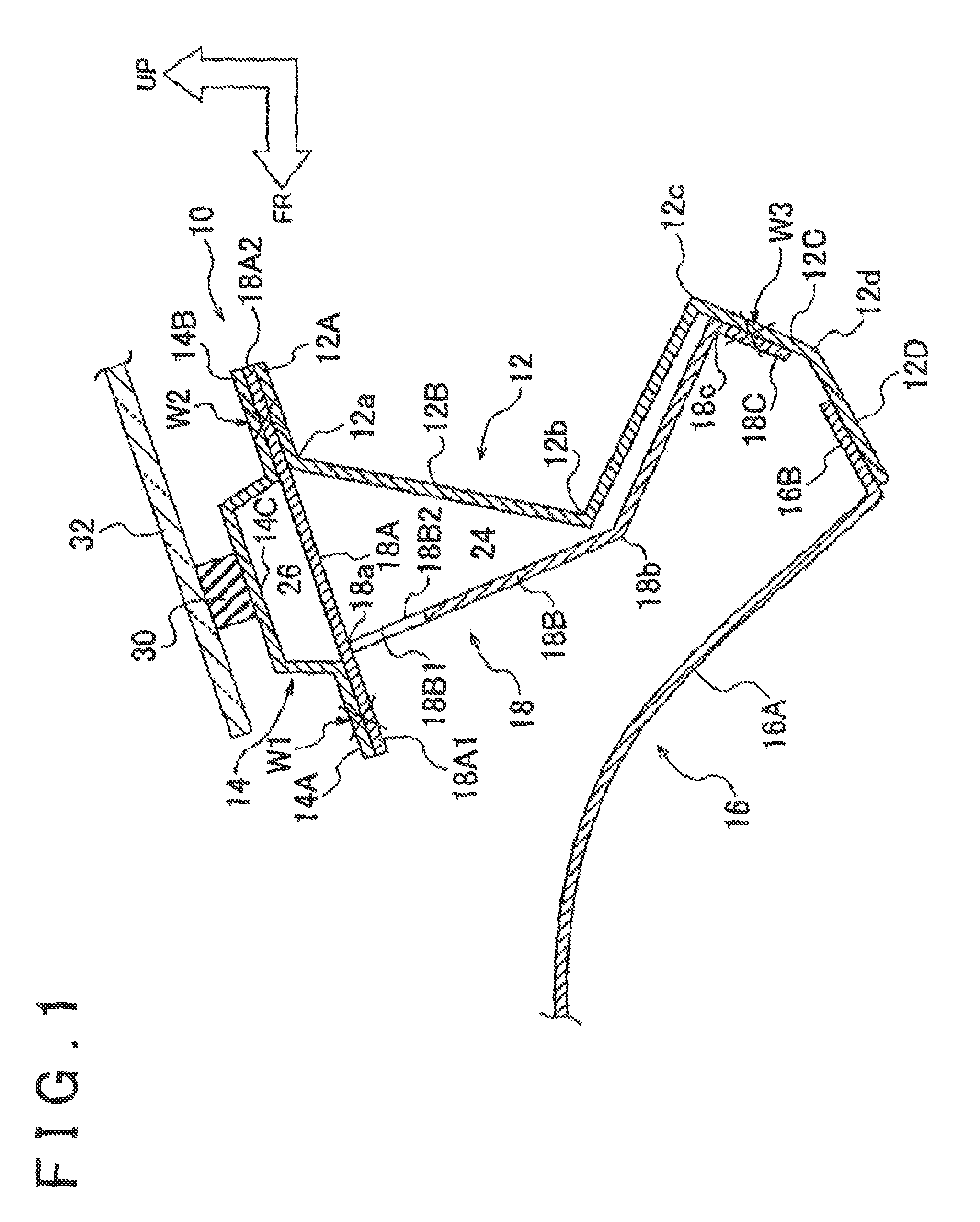
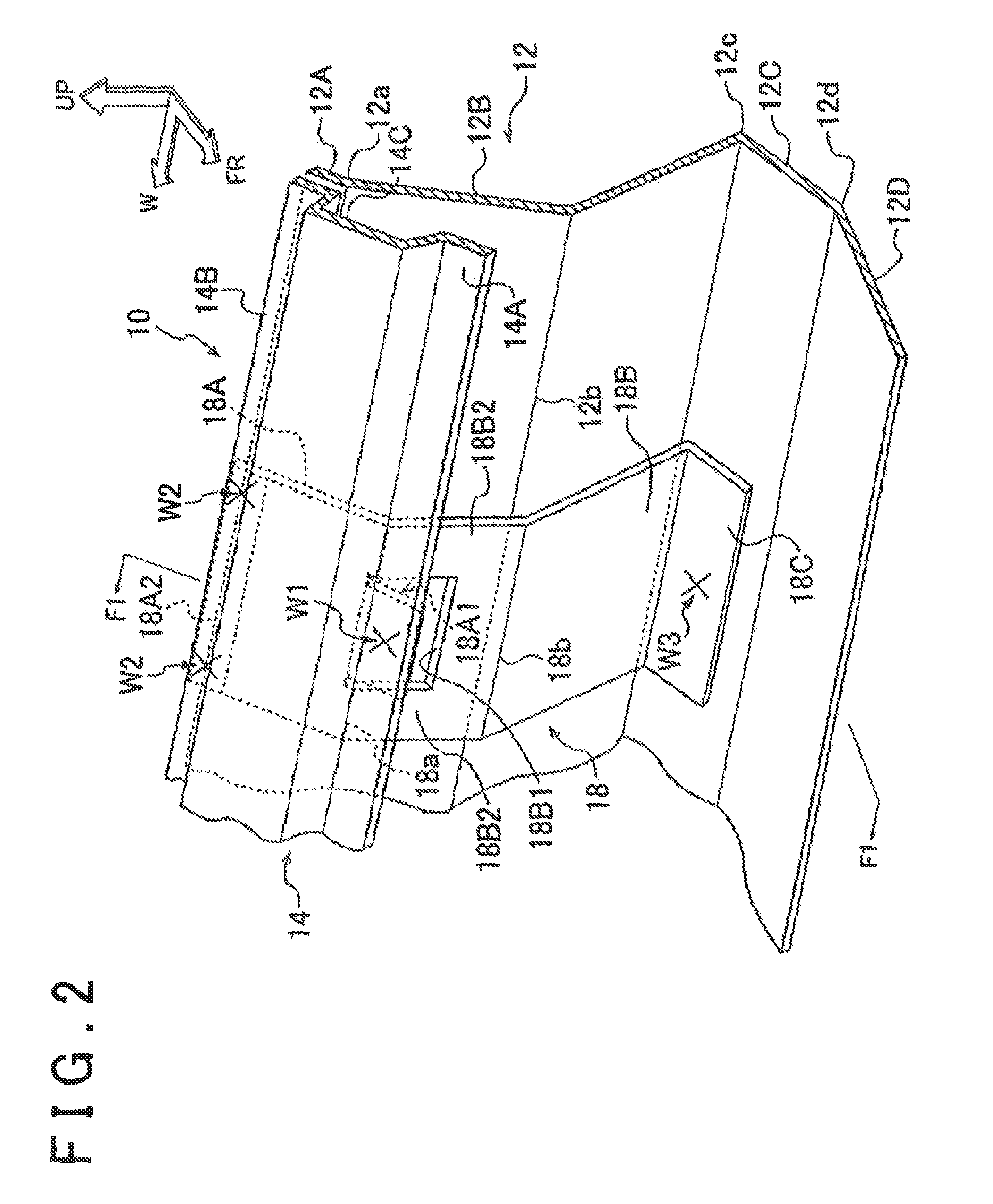
[0045]First of all, the overall configuration of the vehicular cowl structure will be described. As shown in FIGS. 1 to 3, a vehicular cowl structure 10 according to the invention is mainly constituted of a cowl top (which is referred to also as a cowl top outer) 14, a cowl inner panel 12, and a cowl brace 18. These components will be described hereinafter in this order.
[0046]As shown in FIGS. 1 and 2, the cowl top 14 is arranged along a lower end of a front windshield glass 32, with a longitudinal direction of the cowl top 14 coincident with the vehicle width direction. Besides, the cowl top 14 generally has a cross-sectional shape of a hat, with an intermediate portion in the vehicle longitudinal direction protruded upward in the vehicle height as viewed from the side of the vehicle. More specifically, the cowl top 14 is equipped with a front flange portion 14A, a rear flange portion 14B, and an intermediate portion 14C. The front flange portion 14A and the rear flange portion 14B...
second embodiment
[0069]As shown in FIGS. 8A and 8B, in the cowl brace 18 of the vehicular cowl structure 10 according to this second embodiment of the invention, a width dimension WL2 of the flange portion 18A2 as a width dimension of the upper portion 18A of the cowl brace 18 is set larger than a width dimension WL1 of the cowl brace body 18B in the vehicle width direction. In this case, the width dimension WL2 of the flange portion 18A2 is set approximately three times as large as the width dimension WL1 of the cowl brace body 18B. The cowl brace body 18B is formed in the central region of the flange portion 18A2 on the vehicle front side via the flexed portion 18a, and a pair of flange portions 18A1 are disposed on both sides of this cowl brace body 18B in the vehicle width direction respectively. That is, the cowl brace 18 according to this embodiment of the invention is provided with the two (a plurality of) flange portions 18A1 that have been partially cut.
[0070]The cowl brace 18 is basically ...
third embodiment
[0077]As shown in FIGS. 10A and 10B, in the vehicular cowl structure 10 according to this third embodiment of the invention, the width dimension WL2 of the flange portions 18A1 and 18A2 as a width dimension of the upper portion 18A of the cowl brace 18 is set approximately equal to the width dimension WL1 of the cowl brace body 18B in the vehicle width direction. The flange portions 18A1 and 18A2 are formed as platy members that are extended in the vehicle longitudinal direction (the long direction) and in the vehicle width direction (the short direction) respectively, and are integrally formed.
[0078]The cowl brace body 18B and the flange portion 18C are formed as members separate from the flange portions 18A1 and 18A2. A flange portion 18E that is bent from the flexed portion 18a rearward with respect to the vehicle is formed at the upper portion of the cowl brace body 18B, in such a manner as to overlap with the flange portion 18A2. The flange portion 18A2 is connected with the fl...
PUM
 Abstract
Description
Claims
Application Information