Interlocking acetabular fixation screws and their combination with a reverse hip acetabular cup

a technology of acetabular screws and acetabular cups, which is applied in the field of interlocking acetabular fixation screws, can solve the problems of acetabular cups, acetabular cups, and resorption of bone, and achieve the effect of facilitating bone drilling

Active Publication Date: 2016-08-30
HIP INNOVATION TECHONOLOGY LLC
View PDF48 Cites 2 Cited by
  • Summary
  • Abstract
  • Description
  • Claims
  • Application Information

AI Technical Summary

Benefits of technology

[0015]The screw holes in the acetabular cup are also threaded in a tapered fashion to mate with the fine threads of the head of the interlocking acetabular fixation screw. The screw holes of the acetabular cup are also drilled at a specific angle of inclination in order to avoid interference of the drilling instruments, the screws and the screw driver with the central stem of the reverse hip acetabular cup. This feature of the invention also facilitates drilling of the bone and insertion and tightening of the screws.

Problems solved by technology

The main problem with conventional cancellous screws is the fact that they have the tendency to become loose by resorption of bone in the immediate proximity of the screws.
Another problem with conventional cancellous screws is micro motion caused by movement of the acetabular cup under dynamic load, which seems to initiate loosening and subsequently trigger osteolysis that will lead to bone resorption in and loosening of the implant.
Conventional cancellous acetabular screws also lack the rigidity of screw fixation to the cup under dynamic load, leading to micromotion at the point of contact between the acetabular cup and the screws.
As a result, the micromotion leads to fretting and pitting.
In addition, metallic debris and wear particulates may consequently be generated, causing local granulomas around the implant.
However, proper sizing of the screws has not previously been recognized as a factor in the viability of these screws because they have not been used with reverse hip acetabular cups.
Accordingly, existing cancellous bone screws have failed to adequately address the problem of providing a solid acetabular fixation means into a prepared acetabular cavity of a pelvis during a total hip arthroplasty.

Method used


Image

  • Interlocking acetabular fixation screws and their combination with a reverse hip acetabular cup
  • Interlocking acetabular fixation screws and their combination with a reverse hip acetabular cup
  • Interlocking acetabular fixation screws and their combination with a reverse hip acetabular cup

Examples


Embodiment Construction

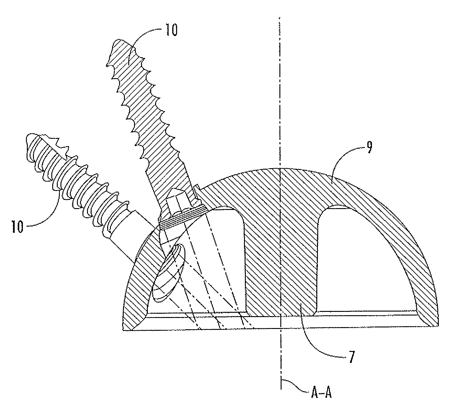
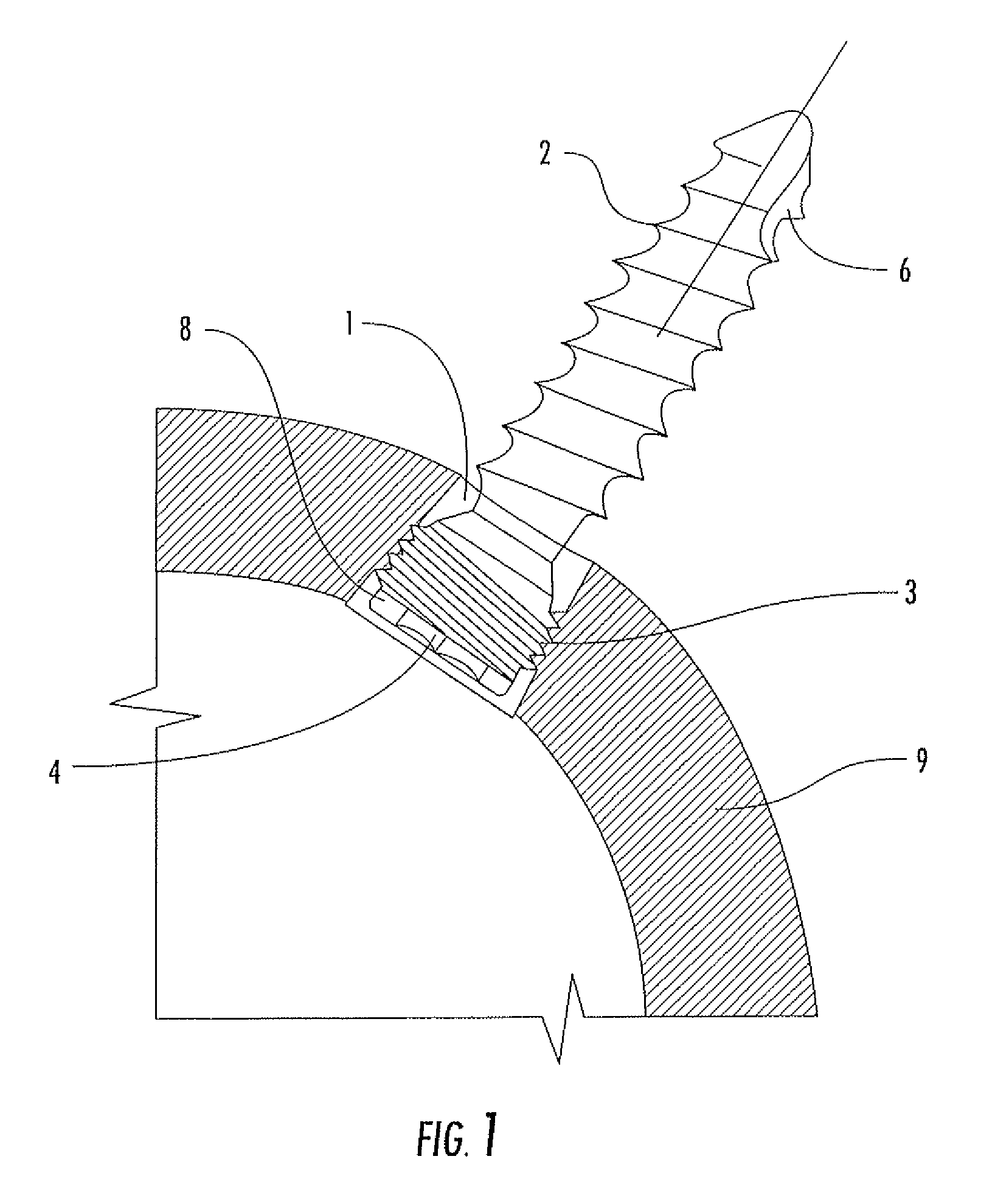
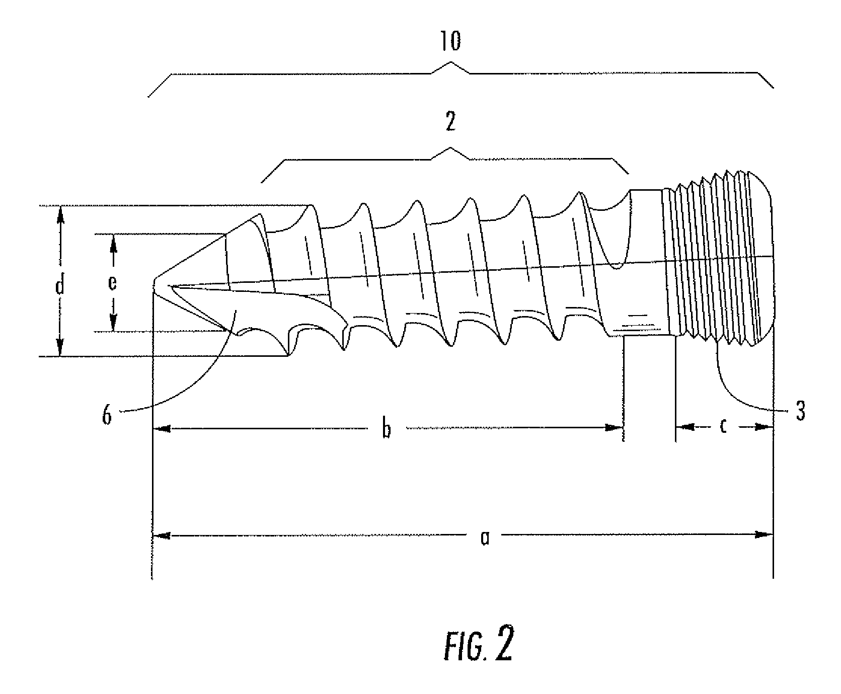
[0021]The attached figures illustrate an interlocking acetabular fixation screw 10, which comprises a specially designed and sized interlocking cancellous screw that will be firmly screwed and locked into threaded, tapered acetabular screw holes or openings 1 in acetabular cup 9. Said screws having a course thread 2 over the length of the screw shank, for optimal screw fixation in the cancellous bone of the pelvis, and a fine locking threaded portion 3 on the screw head. The screw head is preferably cut with a 12 degree taper, but the taper angle can vary from 10 degrees to 15 degrees. The head 8 of the interlocking acetabular fixation screw 10 also provides a hexagonal recess 4 for insertion of a hexagonal screwdriver.

[0022]Referring to FIG. 4, the screw holes or openings in the acetabular cup are drilled at specific angles of inclination in order to avoid interference of the drilling instruments (i.e., the drill guide and / or the drill bit) with the central stem 7 of the acetabular...


PUM


Abstract

Interlocking acetabular fixation screws having a threaded shaft for threading into cancellous bone and a tapered threaded head for threading into tapered threaded screw holes in a reverse hip acetabular cup. The reverse hip acetabular cup has a central stem and the threaded screw holes are drilled at an angle that allows drilling of the bone of the acetabular cavity, placement of the screws and tightening of the screws without touching the central stem and without interference from the central stem.

Description

BACKGROUND OF THE INVENTION[0001]1. Field of the Invention[0002]The present invention relates generally to interlocking acetabular fixation screws and particularly relates to interlocking acetabular fixation screws for providing a solid fixation of an acetabular cup into a prepared acetabular cavity of a pelvis during a total hip arthroplasty. In a further and more specific aspect, the invention has to do with a combination of a new reverse hip acetabular cup having a stem firmly affixed in the concave portion thereof and the interlocking acetabular fixation screws which are used to firmly affix the cup in the acetabular cavity.[0003]2. The Related Art[0004]It can be appreciated that the securing of an acetabular cup with ordinary screws is known in the prior art. For example, acetabular cups are fixed using conventional cancellous screws with flat heads having a recess for insertion and extraction with common screwdrivers.[0005]Other means of fixation include asperities and voids a...

Claims


Application Information

Patent Timeline
Patent Type & Authority Patents(United States)
IPC IPC(8): A61F2/34A61B17/86A61B17/80A61F2/30
CPCA61F2/34A61B17/8057A61F2002/30332A61F2002/3401A61F2002/3483A61B17/8605A61F2002/3446
Inventor TERMANINI, ZAFER
Owner HIP INNOVATION TECHONOLOGY LLC
Why Eureka
Try Eureka