

Anchoring kit for a drilling machine
a drilling machine and kit technology, applied in the field of soil drilling, can solve the problems of difficult for an operator to have a standard machine and a specific machine on the same construction site, and the drilling machine model available on the market is not suitable for hard or very hard soil, so as to avoid the deflection of the drilling module
- Summary
- Abstract
- Description
- Claims
- Application Information
AI Technical Summary
Benefits of technology
Problems solved by technology
Method used
Image

Examples
first embodiment
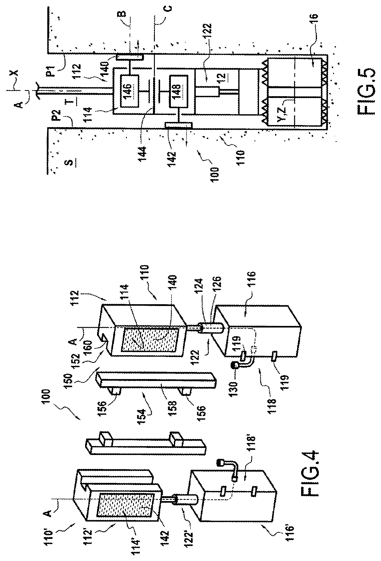
[0071]In FIG. 4, an anchoring kit 100 according to the invention is illustrated.
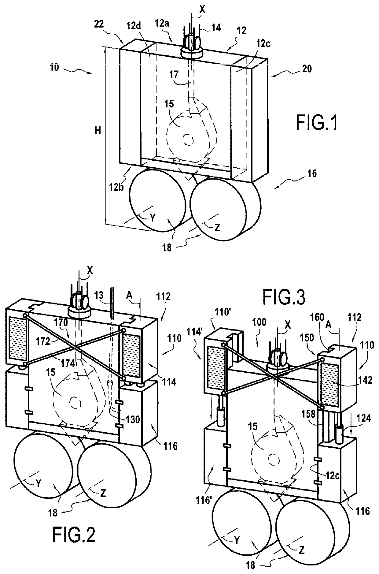
[0072]The anchoring kit 100 includes a first anchoring module 110 which comprises a first part 112 including an anchoring device 114 for immobilizing the first part in the soil.
[0073]The anchoring device 114 will be described in more detail below.
[0074]The first anchoring module 114 further includes a second part 116 which includes a fixing device 118 for fixing the second part 116 to the frame 12. In this example, the fixing device 118 includes for example bolts 119.
[0075]It can also be observed that the second part 116 cooperates with the first part 112. More specifically, the first anchoring module 110 includes a displacement device 122 for moving the second part 116 relative to the first part 112 along a first direction A. It can be observed that, when the first anchoring module is mounted to the frame, the first direction A is parallel to the longitudinal direction X of the frame, these two directio...
second embodiment
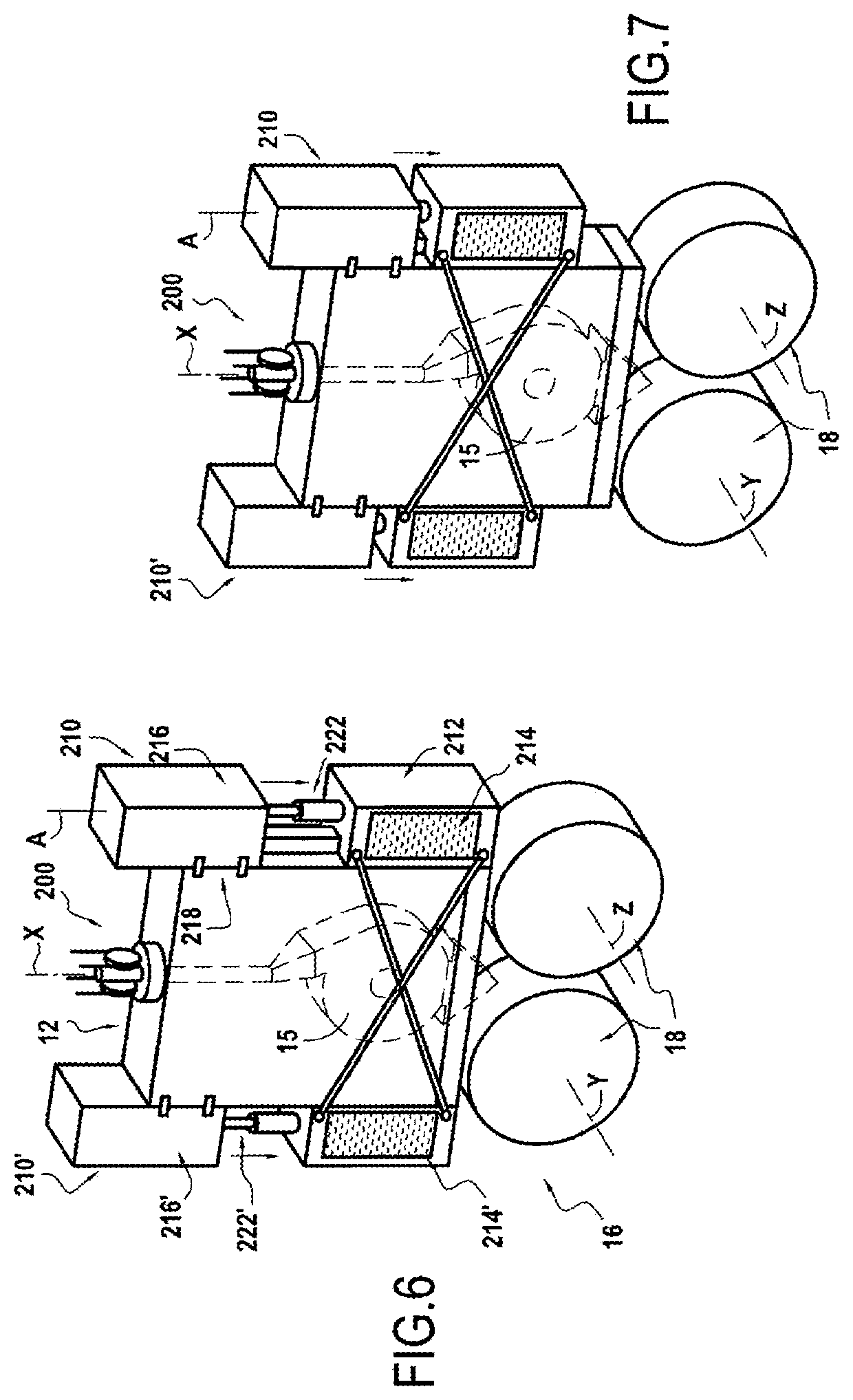
[0087]In the example of FIGS. 2 to 4, the second part 116 of the first anchoring module is disposed between the first part 112 and the drilling module 16. Thanks to FIGS. 6 and 7, the anchoring kit 200 according to the present invention will now be described.
[0088]The anchoring kit 200 is mounted on the drilling machine 10 illustrated in FIG. 1. Like the first embodiment, the anchoring kit 200 includes a first anchoring module 210 which comprises a first part 212 including an anchoring device 214 for immobilizing the first part 212 in the soil, as well as a second part 216 including a fixing device 218 for fixing the second part to the frame 12, the second part 216 cooperating with the first part 212.
[0089]The anchoring kit 200 also includes a displacement device 222 for moving the second part 216 relative to the first part 212 along the first direction A.
[0090]It is understood from FIGS. 6 and 7 that the anchoring kit 200 according to the second embodiment is very similar to the an...
third embodiment
[0091]Thanks to FIGS. 8 and 9, the anchoring kit 300 according to the invention will now be described. Here again, the anchoring kit 300 is mounted on the drilling machine 10 illustrated in FIG. 1.
[0092]The third embodiment of the anchoring kit 300 differs from the first embodiment in that the connecting device 370 which links together the first parts 312, 312′ of the first and second anchoring modules 310, 310′ includes a passage 372 for guiding the displacement of the frame 12 along the longitudinal direction X. Seen otherwise, the first parts 312, 312′ of the first and second anchoring modules 310, 310′ form a single piece. In this example, this single part includes an anchoring device 314 provided with a pair of large anchoring pads 315 which extend along the width of the drilling machine. Also, in this example, the second part 316 of the first anchoring module 310 is also disposed between the first part 312 of the first anchoring module 310 and the drilling module 16.
[0093]This...
PUM
 Abstract
Description
Claims
Application Information