Method for stereo visual odometry using points, lines and planes

a visual odometer and point technology, applied in the field of computer vision, can solve problems such as difficult to extend existing cases

Inactive Publication Date: 2016-08-30
MITSUBISHI ELECTRIC RES LAB INC
View PDF9 Cites 10 Cited by
  • Summary
  • Abstract
  • Description
  • Claims
  • Application Information

AI Technical Summary

Problems solved by technology

It is not straightforward to extend the existing cases because careful analysis of the geometric primitives is required to compute the motion parameters.

Method used


Image

  • Method for stereo visual odometry using points, lines and planes
  • Method for stereo visual odometry using points, lines and planes
  • Method for stereo visual odometry using points, lines and planes

Examples


Embodiment Construction

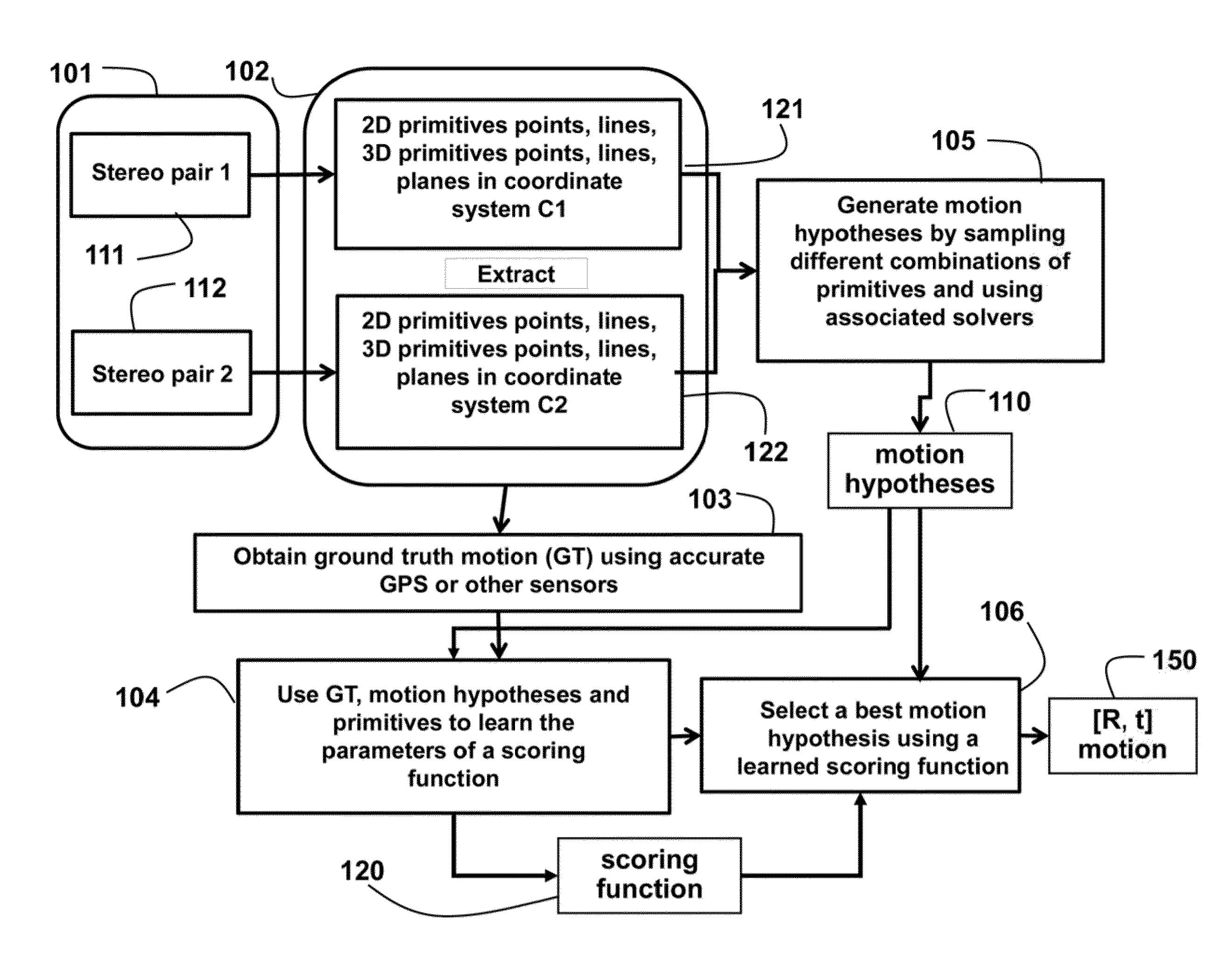
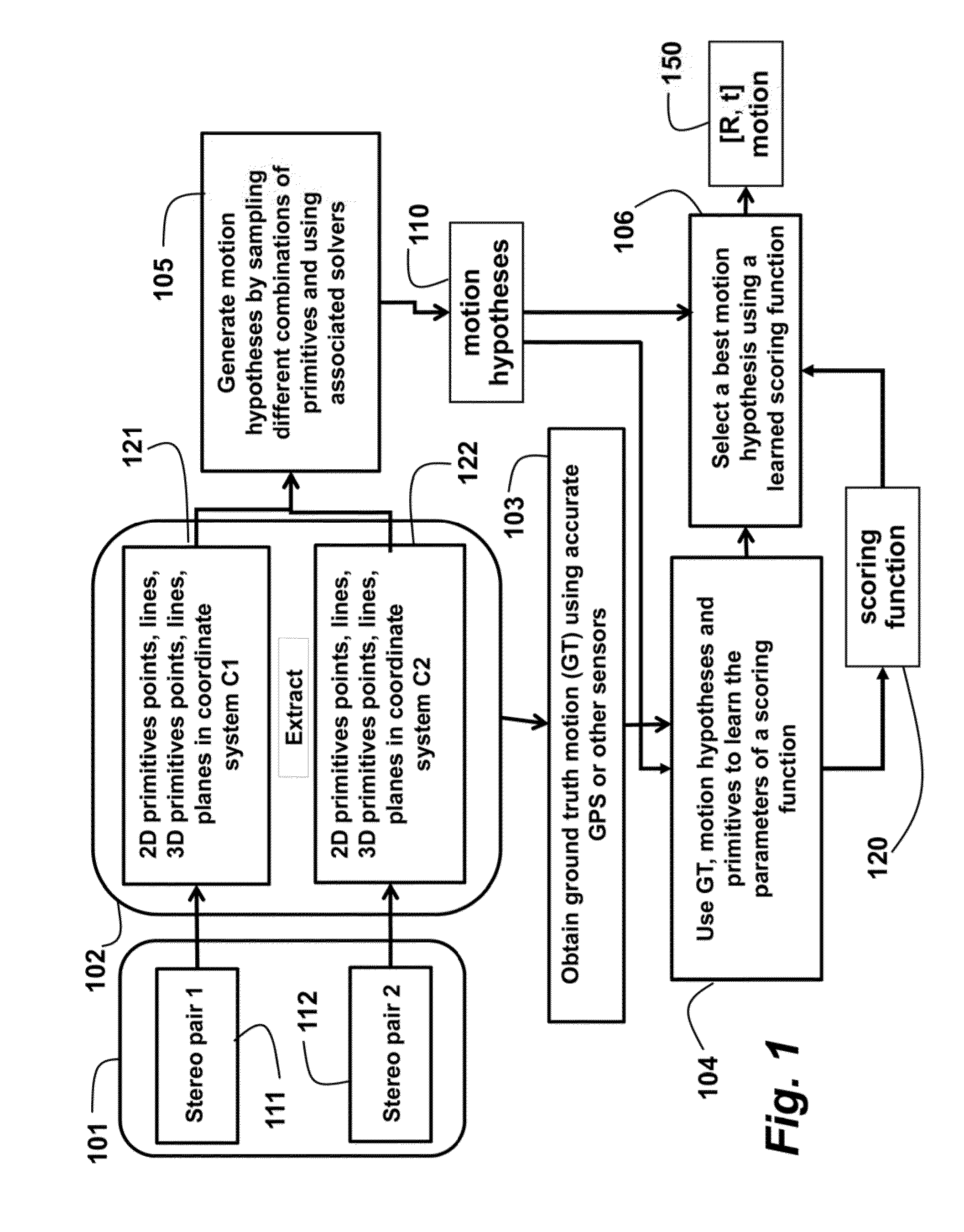
[0012]As shown in FIG. 1, the embodiments of the invention provide a method for estimating motion. Input 101 to the method is two pairs 111 and 112 of stereo images (Left1, Right1) and (Left2 Right2) in two coordinate systems C1 and C2 respectively. Each stereo image can be acquired by a pair of red, green and blue (RGB) cameras calibrated with each other. The embodiments of the invention, determine rotational and translational motion (R,t) 150 between C1 and C2 using the two pairs of stereo images.

[0013]It is noted that the images can also be acquired by an RGBD sensor. Hence, generally the images can be considered three-dimensional (3D) images, which can either be represented by a stereo pair or a single RGBD image. It is also possible to use more than two cameras, e.g., a trinocular stereo camera, to increase the accuracy of the depth information.

[0014]For each of the four images in two stereo pairs of images or 3D images, 2D points and 2D lines are extracted 102, From the first ...


PUM


Abstract

A method determines a motion between a first and second coordinate system, by first extracting a first set of primitives from a 3D image acquired in the first coordinate system from an environment, and extracting a second set of primitives from a 3D image acquired in the second coordinate system from the environment. Motion hypotheses are generated for different combinations of the first and second sets of primitives using a RANdom SAmple Consensus procedure. Each motion hypothesis is scored using a scoring function learned using parameter learning techniques. Then, a best motion hypothesis is selected as the motion between the first and second coordinate system.

Description

FIELD OF THE INVENTION[0001]The invention relates generally to computer vision, and more particularly to determining motion between two coordinate systems using points, lines and planes as geometric primitives, where each coordinate system corresponds to a camera coordinate system of a stereo camera or a red, green, blue and depth (RGBD) sensor.BACKGROUND OF THE INVENTION[0002]Visual odometry uses data acquired by moving sensors to estimate change in motion over time. Numerous methods are known for estimating the motion using geometric primitives such as points, lines and planes. For example, one can determine the motion using correspondences between 3D points in one coordinate system to another coordinate system. As expected, different types of solvers have different advantages and disadvantages, which mean that failure modes of one particular method may not be present in another one.[0003]One method uses three 2D to 3D point correspondences to obtain motion between stereo pairs. 3...

Claims


Application Information

Patent Timeline
Patent Type & Authority Patents(United States)
IPC IPC(8): G06K9/00G06T17/10G06T3/00G06K9/52G06T7/20G06K9/62
CPCG06K9/52G06K9/6256G06T3/00G06T7/20G06T17/10G06T7/2033G06T2207/10021G06T2207/10028G06T2207/20021G06T2207/20081G06T7/246G06F18/214
Inventor RAMALINGAM, SRIKUMARTAGUCHI, YUICHIANTUNES, MICHELURTASUN, RAQUEL
Owner MITSUBISHI ELECTRIC RES LAB INC
Why Eureka
Try Eureka