
Systems and methods for exporting application details using appflow

a technology of application details and appflow, applied in the field of data communication networks, can solve the problems of not giving finer flow information such as at the http transaction level, flow definitions that do not necessarily match application-level end-to-end streams, and fail to address session or application layer transaction boundary or other fine details, so as to achieve the effect of not affecting administrative processes

Active Publication Date: 2016-08-30
CITRIX SYST INC
View PDF12 Cites 7 Cited by
  • Summary
  • Abstract
  • Description
  • Claims
  • Application Information

AI Technical Summary

Benefits of technology

[0008]The present disclosure is directed towards systems and methods for monitoring application level flow for database applications served by a cluster of servers. An application flow monitor may receive and distribute write requests of a client to at least one master server and read requests of the client to one or more slave servers, based on load balancing or similar policies. The application flow monitor may receive responses from the recipient server and may aggregate the requests and responses into Internet Protocol Flow Information Export (IPFIX) messages that may describe the entire communication flow for the application. Accordingly, application flow statistics may be monitored, regardless of which server was involved in any particular request / response exchange, allowing scalability without impairment of administrative processes.
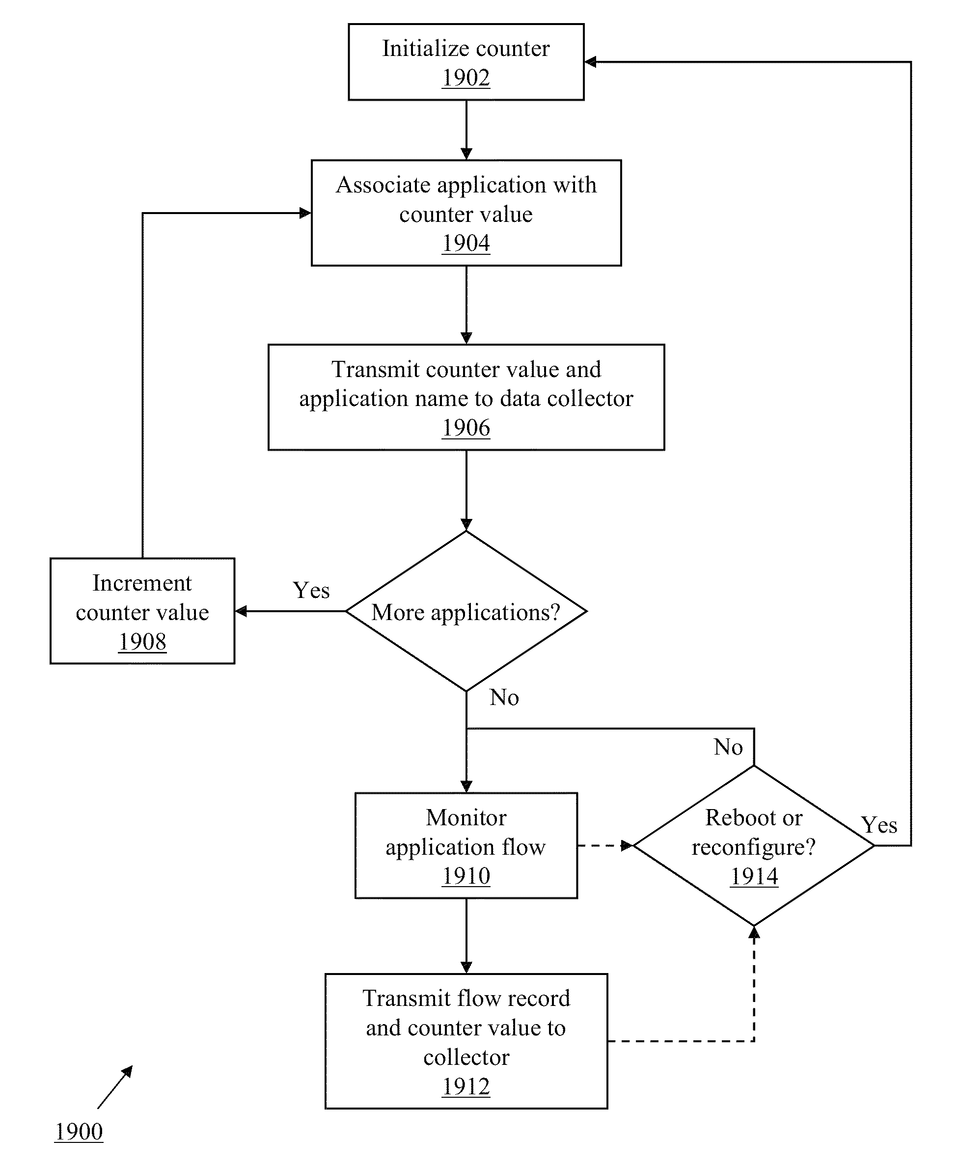
[0010]In one aspect, the present disclosure is directed to a method for lightweight identification of flow information by application. The method includes maintaining, by a flow monitor executed by a processor of a device, a counter. The method also includes associating, by the flow monitor, an application with the value of the counter. The method further includes transmitting, by the flow monitor to a data collector executed by a second device, the counter value and a name of the application. The method also includes monitoring, by the flow monitor, a data flow associated with the application to generate a data record. The method also includes transmitting the data record, by the flow monitor to the data collector, the data record including an identification of the application consisting of the counter value.
[0013]In another aspect, the present disclosure is directed to a method for lightweight identification of flow information by application. The method includes receiving, by a data collector executed by a processor of a device, from a second device, a name of an application and a value of a counter maintained by a flow monitor executed by the second device. The method also includes mapping, by the data collector, the received name of the application to the counter value. The method further includes receiving, by the data collector from the flow monitor, a data flow record including an identification of the application consisting of the counter value. The method also includes re-associating the received data flow record with the name of the application, by the data collector, responsive to the mapping of the name of the application to the counter value.

Problems solved by technology

However, while SNMP is extensible and can incorporate new management elements, it does not give finer flow information such as at the HTTP transaction level.
As noted in RFC 5101, however, the flow definition does not necessarily match application-level end-to-end streams.
Typically, these include values aggregated from multiple higher layer communications, and accordingly, fail to address session or application layer transaction boundaries or other fine detail.
Other techniques exist for capturing application layer network information, but each have drawbacks.
For example, HTML injection and logging lacks flexibility and extensibility in adding new elements, and requires proprietary applications on both ends of a communication in order to capture data.
Port mirroring provides fine detail, but is highly demanding of both network bandwidth and CPU usage.

Method used


Image

  • Systems and methods for exporting application details using appflow
  • Systems and methods for exporting application details using appflow
  • Systems and methods for exporting application details using appflow

Examples


Embodiment Construction

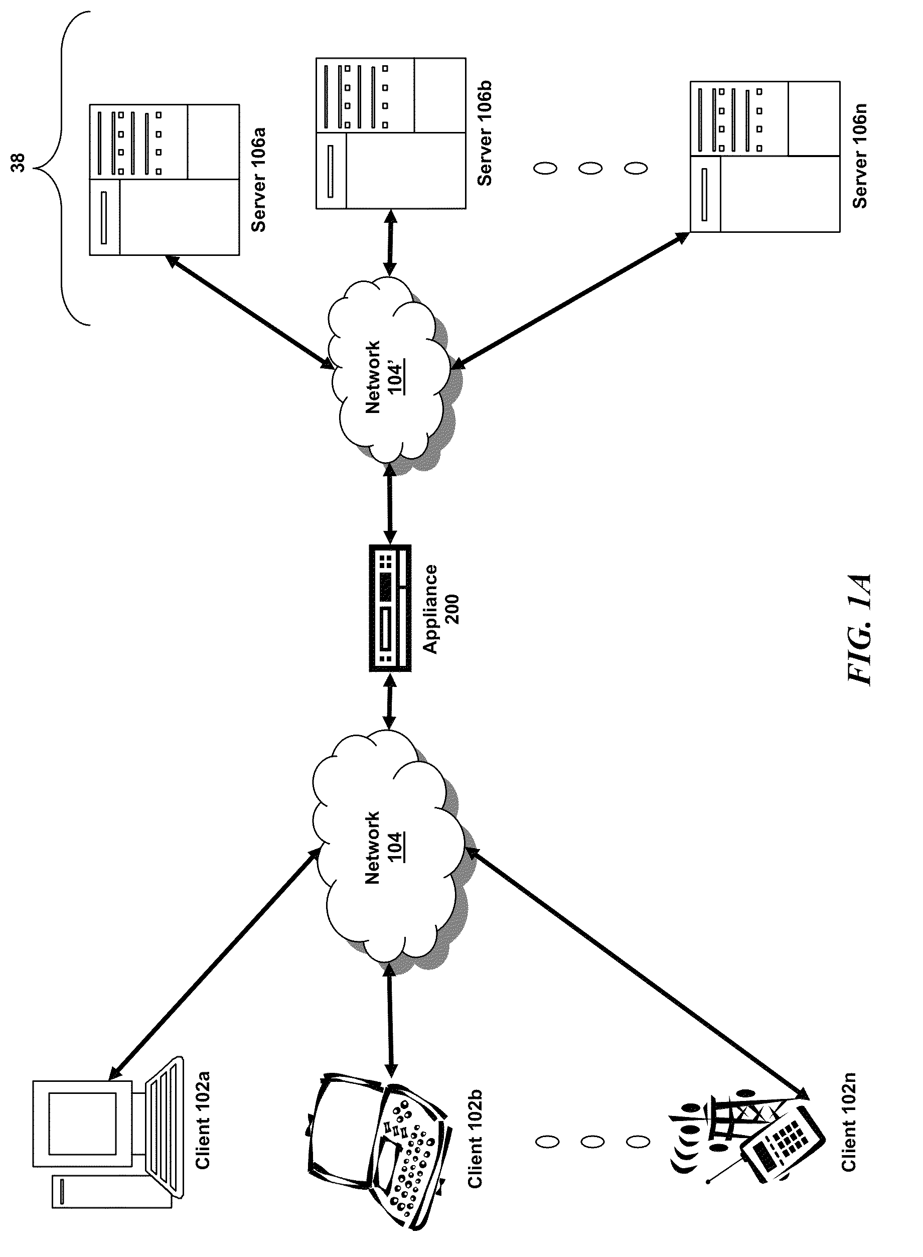
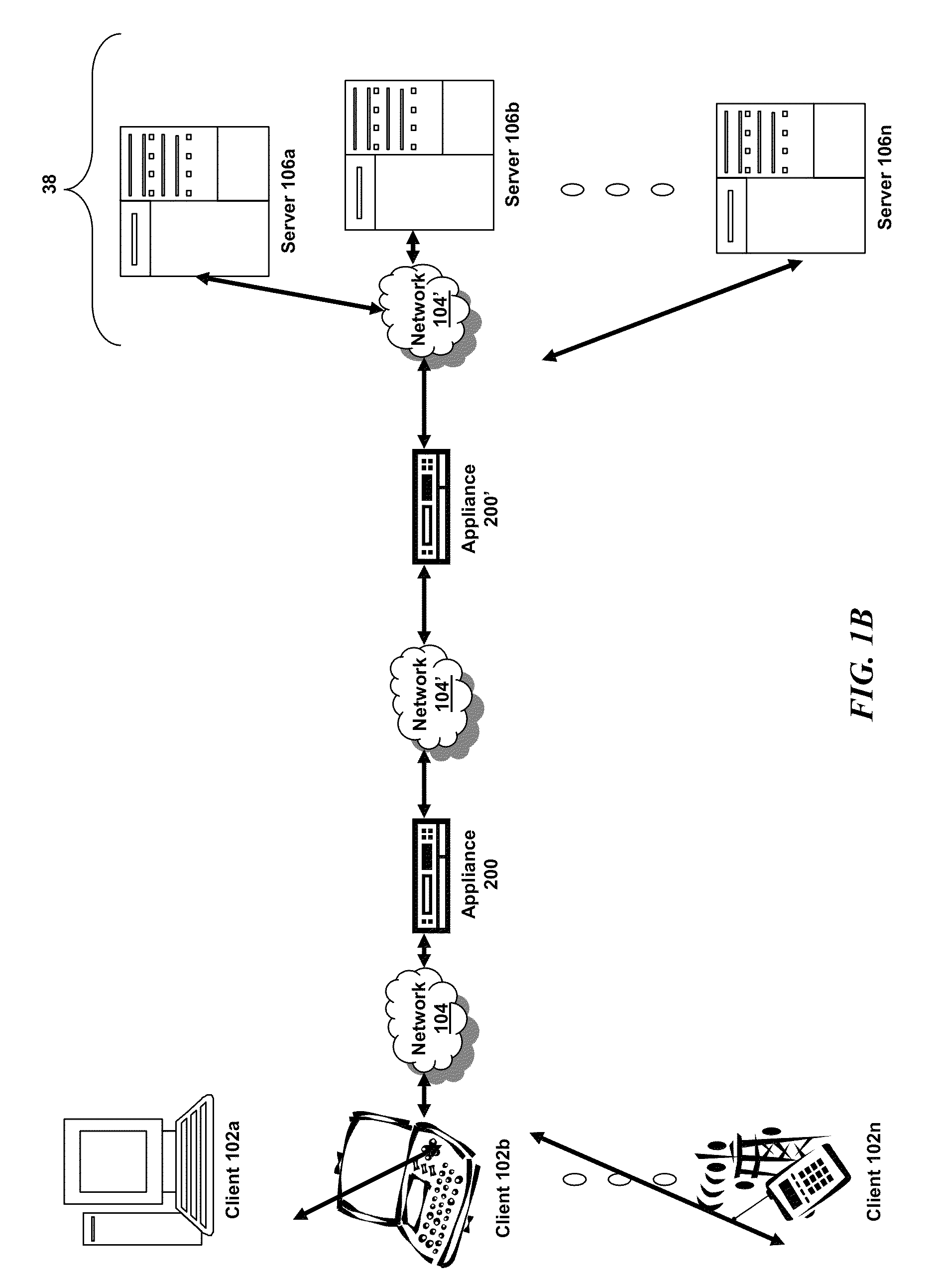
[0061]For purposes of reading the description of the various embodiments below, the following descriptions of the sections of the specification and their respective contents may be helpful:[0062]Section A describes a network environment and computing environment which may be useful for practicing embodiments described herein;[0063]Section B describes embodiments of systems and methods for delivering a computing environment to a remote user;[0064]Section C describes embodiments of systems and methods for accelerating communications between a client and a server;[0065]Section D describes embodiments of systems and methods for virtualizing an application delivery controller;[0066]Section E describes embodiments of systems and methods for providing a multi-core architecture and environment;[0067]Section F describes embodiments of systems and methods for tracking application layer flow via a multi-connection intermediary device;[0068]Section G describes embodiments of systems and methods...


PUM


Abstract

The present disclosure is directed towards systems and methods for lightweight identification of flow information by application. A flow monitor executed by a processor of a device may maintain a counter. The flow monitor may associate an application with the value of the counter and transmit, to a data collector executed by a second device, the counter value and a name of the application. The flow monitor may monitor a data flow associated with the application to generate a data record. The flow monitor may transmit the data record to the data collector, the data record including an identification of the application consisting of the counter value and not including the name of the application. The data collector may then re-associate the data record with the application name based on the previously received counter value.

Description

FIELD[0001]The present application generally relates to data communication networks. In particular, the present application relates to systems and methods for identifying applications in flow records via a lightweight identification protocol.BACKGROUND[0002]Traditionally, different methods have been used for information collection and management of networks and devices. Most popular is the older Simple Network Management Protocol (SNMP). However, while SNMP is extensible and can incorporate new management elements, it does not give finer flow information such as at the HTTP transaction level. Instead, SNMP provides only aggregated device-level information.[0003]Similarly, the newer IP Flow Information Export, or IPFIX, protocol also focuses on lower level flow information. IPFIX is a universal standard for exporting Internet Protocol flow information from routers, switches, probes, and other intermediary devices. IPFIX is defined in Internet Engineering Task Force (IETF) RFCs 5101 a...

Claims


Application Information

Patent Timeline
Patent Type & Authority Patents(United States)
IPC IPC(8): G06F15/16H04L12/26G06F9/44H04L29/06H04L29/08G06F9/455
CPCH04L43/04G06F9/45533H04L43/026H04L43/028G06F9/4445H04L63/102H04L67/146G06F11/3495G06F11/006G06F11/3433H04L63/168G06F2201/80G06F2201/815G06F2201/87G06F2201/875G06F2201/88G06F9/452
Inventor ANNAMALAISAMI, SARAVANAJOSHI, RAJESHGARG, SOVITNEERGUNDA, ARVIND
Owner CITRIX SYST INC
Learn More