Impression tray set for edentulous jaw

a technology for edentulous jaws and impression tray sets, which is applied in the field of impression tray sets for edentulous jaws, can solve the problems of inability to obtain data regarding bite position and height, and achieve the effects of preventing inaccurate impressions, convenient pressing against alveolar ridges, and quick and easy manufacturing

Active Publication Date: 2016-09-06
GC CORP
View PDF22 Cites 9 Cited by
  • Summary
  • Abstract
  • Description
  • Claims
  • Application Information

AI Technical Summary

Benefits of technology

[0016]An impression tray set for edentulous jaw according to the present invention includes a maxillary impression tray and a mandibular impression tray respectively including a tray main body having a U-shaped groove on which an impression material is to be applied on a front surface side thereof, an engaging part formed on a back surface of the U-shaped groove in a position corresponding to an alveolar ridge of front teeth, and a handle part that is detachably connected to the engaging part. Because the handle part can be removed when taking an impression using the impression tray set, and it is possible to prevent an inaccurate impression caused by the handle part hitting a lip. In addition, each of the maxillary impression tray and the mandibular impression tray includes projecting parts being provided on the back surface, at left and right portions of the U-shaped groove in a position corresponding to an alveolar ridge from a first molar part to a premolar part, the projecting parts being used for determining bite position and height in a state in which at least a part of flat top surfaces of the projecting parts contact each other when taking an impression, a pair of projecting parts can be arranged on the left and right at approximately an intermediate part between the front teeth and the molars. Hence, by adjusting positions in a state in which at least a part of the flat top surfaces of the projecting parts contact each other, positions of the maxillary impression tray and the mandibular impression tray can be determined at various bite positions and heights, and processes that need to be carried out separately, such as measuring the bite position and height, can be omitted, and the full denture base can be manufactured quickly and with ease. Further, when the handle part is removed when taking the impression, the impression material can easily be pressed against the alveolar ridge by pushing the projecting parts by fingers, without causing the excess impression material to stick to a hand.
[0017]In the above described configuration, when the projecting part is formed so that a longitudinal direction thereof matches a ridge line direction at the back surface of the U-shaped groove, a length thereof in the longitudinal direction is 5 mm to 20 mm, and a width in a width direction is 3 mm to 10 mm, it is possible to prevent a state in which the maxillary and mandibular projecting parts do not make contact due to the patient's jaw position. Furthermore, when relatively small projecting parts are used, it is preferable in that the projecting parts can more easily be moved even to the bite position and height where the projecting parts are inclined and held at the inclined position. In addition, when the projecting part is formed by a hollow tubular part integrally formed on each of the maxillary impression tray and the mandibular impression tray, and a bite height adjusting piece that is inserted into and retained within a hole part of the tubular part and has a part corresponding to the top surface, the height of the projecting part can be changed with ease, and it is preferable in that accurate bite position and height can easily be determined.

Problems solved by technology

However, this impression tray is merely for taking the impression of the alveolar ridge (refer to paragraph 0001 of specification of Patent Document 1), and no data can be obtained with respect to the bite position and height.

Method used


Image

  • Impression tray set for edentulous jaw
  • Impression tray set for edentulous jaw
  • Impression tray set for edentulous jaw

Examples


Embodiment Construction

[0025]A detailed description will hereinafter be given of the impression tray set for edentulous jaw according to the present invention, by referring to the drawings.

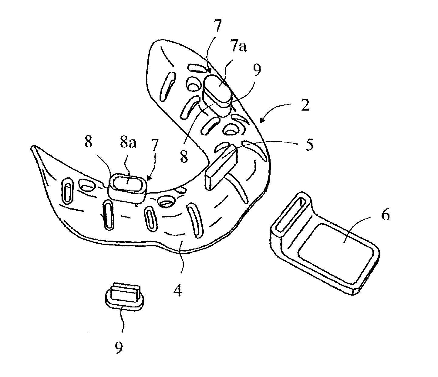
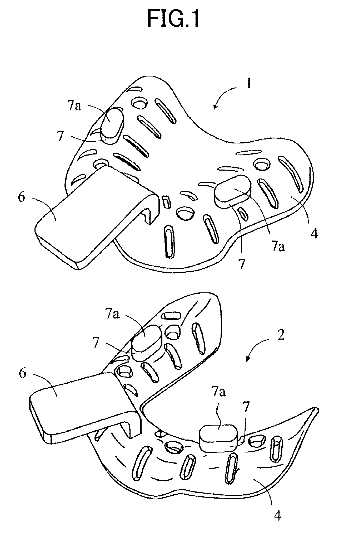
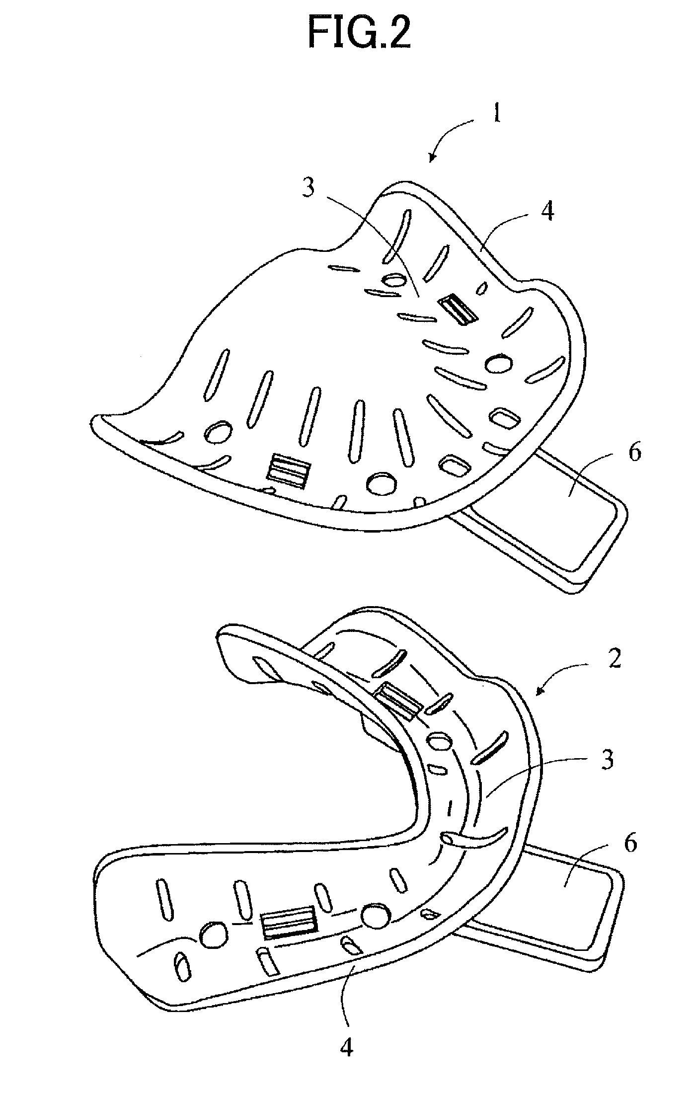
[0026]In the drawings, an impression tray set for edentulous jaw according to the present invention is formed by a maxillary impression tray 1 and a mandibular impression tray 2. Each of the maxillary impression tray 1 and the mandibular impression tray 2 is formed by a tray main body 4 and a handle part 6 which will be described later.

[0027]A U-shaped groove 3 is to be used for being applied with an impression material thereon. And the tray main body 4 has the U-shaped groove 3 on a front surface side thereof. As illustrated in FIGS. 1-7, the tray main body 4 is preferably formed with elongated holes and the like through which the impression material is pushed out and combined into one piece. In addition, as illustrated in FIGS. 1-5, the mandibular impression tray 2 needs to have a shape that does not have a part corre...


PUM


Abstract

An impression tray set for edentulous jaw is formed by a maxillary impression tray and a mandibular impression tray respectively including a tray main body having a U-shaped groove on which an impression material is to be applied on a front surface thereof, an engaging part formed on a back surface of the U-shaped groove in a position corresponding to an alveolar ridge of front teeth, and a handle part detachably connected to the engaging part. Each of the maxillary and mandibular impression trays includes projecting parts provided on the back surface at portions corresponding to an alveolar ridge from a first molar part to a premolar part. The projecting parts determine bite position and height in a state in which at least a part of flat top surfaces of the projecting parts contact each other when taking an impression.

Description

TECHNICAL FIELD[0001]The present invention relates to an impression tray set for edentulous jaw, including a pair of a maxillary impression tray and a mandibular impression tray for use in taking an intraoral impression, and capable of simultaneously recording bite position and height when taking the impression.BACKGROUND ART[0002]Generally, in odontotherapy, when taking an intraoral impression in a preparation stage of manufacturing prostheses, an impression material such as silicone impression materials, alginate impression materials, and the like is used. An impression tray is used to intraorally hold such an impression material. The impression material is applied on the impression tray that is inserted into an oral cavity of a patient, and after the impression material is pressed for taking an impression and is set, the impression tray is removed from the oral cavity of the patient in a state in which the set impression material is integrally held on the impression tray.[0003]Wh...

Claims


Application Information

Patent Timeline
Patent Type & Authority Patents(United States)
IPC IPC(8): A61C9/00A61C19/05A61C8/00
CPCA61C9/0006A61C8/0001A61C19/05
Inventor SUGA, TAKEOITODA, MASATAKAKAMOHARA, HIROSHI
Owner GC CORP
Why Eureka
Try Eureka