Electrical connector

a technology of electrical connectors and connectors, applied in the direction of coupling devices, two-part coupling devices, electrical apparatus, etc., can solve the problems of complex terminal shapes, less flexibility in design, and complex terminal shapes, and achieve the effect of not making the shapes of the terminals complicated, large floating, and large misalignment between the connectors

Active Publication Date: 2016-10-25
HIROSE ELECTRIC GROUP
View PDF6 Cites 7 Cited by
  • Summary
  • Abstract
  • Description
  • Claims
  • Application Information

AI Technical Summary

Benefits of technology

[0020]According to the first aspect of the invention, prior to fitting the connectors, when the connector for a circuit board and the mating connector are not aligned relative to each other in the arrangement direction of the connecting members, if the mating connector abuts the casing members in the connector fitting direction in the connector fitting process, the casing members make at least one of displacements, straight displacement or angular displacement towards the side of positional displacement, for the amount of the displacement. Therefore, as the casing members displace, the deformable portions of the terminals deform in the sheet thickness direction of the terminals. As a result, the casing members and the connecting members float according to the misalignment between the connectors. Consequently, the guiding surfaces guide the mating terminals to the positions so as to be able to contact with the contact portions. As a result, it is achievable to secure satisfactory fitting / connecting state of the connectors.
[0021]As described above, according to the first aspect of the invention, the terminals respectively provided in the plurality of connecting members are not held all together at positions near the contact positions of the terminals. Therefore, upon floating, the deformable portions of the terminals in the respective connecting members deform to bend towards the side where misalignment with the mating connector occurs. More specifically, areas from the deformable portions of the terminals to the other ends (ends where the contact portions are provided) displace to tilt having the deformable portions as fulcrums. Therefore, according to the first aspect of the invention, the amount of displacements of the contact portions of the terminals are greater in the direction of the misalignment, in comparison with a case of straight displacement in the misalignment direction without tilting of the contact portions of the terminal as in the conventional connector. In other words, according to the first aspect of the invention, without increasing the total lengths of the terminals, which are in turn the connector's size, and without making the shapes of the terminals complicated, it is achievable to obtain large floating. In addition, it is also achievable to manage large misalignment between the connectors.
[0024]With such movable holding members, upon floating, when the movable holding members receive the pressing force at the pressure-receiving portions from the casing members, which are displaced straight or angularly, the movable holding members make angular displacement as described above. In addition, the terminals displace so as to tilt having the deformable portions as fulcrums. The movable holding portions are provided in the middle parts between the contact portions and deformable portions of the terminals. In other words, the deformable portions are provided between the stationary holding members and the movable holding members. The terminals will not flex at the parts (the held portions) that are held by the stationary holding members and the parts that are held by the movable holding members. Therefore, it is achievable to bend to deform the deformable portions by securely focusing the stress onto the deformable portions upon floating of the connector.
[0026]In transmission of electrical signals by a connector, normally, impedance change is preferred to be small over the range in the longitudinal direction of the terminals so as to minimize loss of the electrical signals. According to the third aspect of the invention, the deformable portions have to deform in their thickness direction upon floating. For this reason, the deformable portions are not held by other members and exposed to the air. Therefore, in order to match impedance with that at parts held by the movable holding members, i.e., parts where at least a part of circumferential surface is covered by the movable holding members, it is necessary to increase the width of the deformable portions to be greater than the width of the parts held by the movable holding members.
[0030]Therefore, even when there is misalignment between connectors in the arrangement direction of the connecting members in a connector fitting process or in a connector fitted state, the connectors can float by tilting displacement of the terminals with the deformable portions being fulcrums. As a result, without increasing the total length of each of the terminals and in turn the size of the connector, and without making the shapes of the terminals complicated, it is achievable to obtain large floating and to manage large misalignment between the connectors.

Problems solved by technology

As a result, there is less flexibility in the design, and it is not preferred.
Moreover, the terminals are bent to the 90-degree rotated S-shapes, and thereby the terminals have complicated shapes.
The complicated shapes of the terminals increase the cost and labor upon manufacturing of the terminals.
In addition, since the signal transmission path is curved, for example, when signals to be transmitted between the connectors are high-speed signals, there is concern of adverse impact on the signal transmission speed.

Method used


Image

  • Electrical connector
  • Electrical connector
  • Electrical connector

Examples


Embodiment Construction

[0044]Hereunder, an embodiment of the present invention will be described with reference to the accompanying drawings.

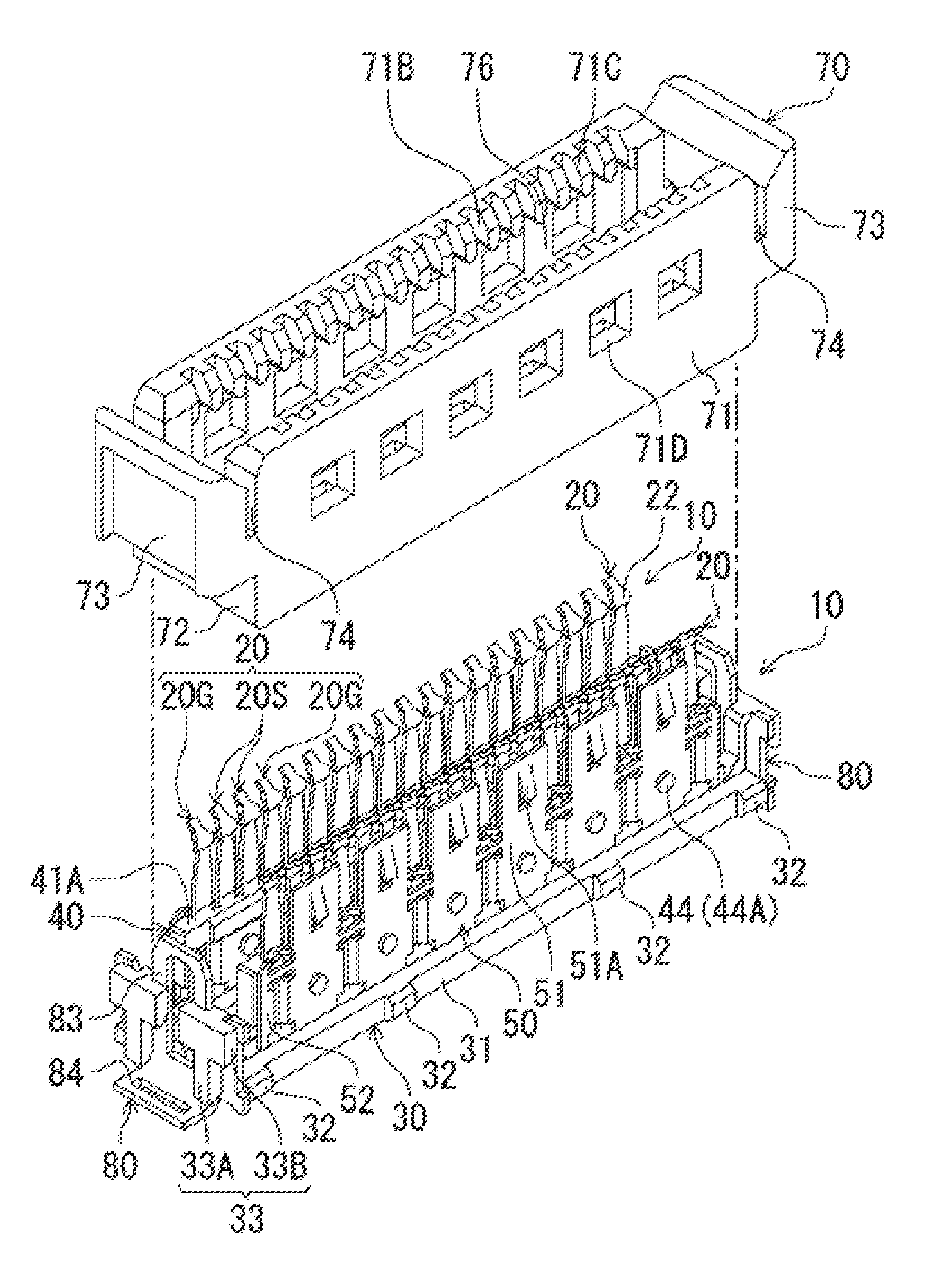
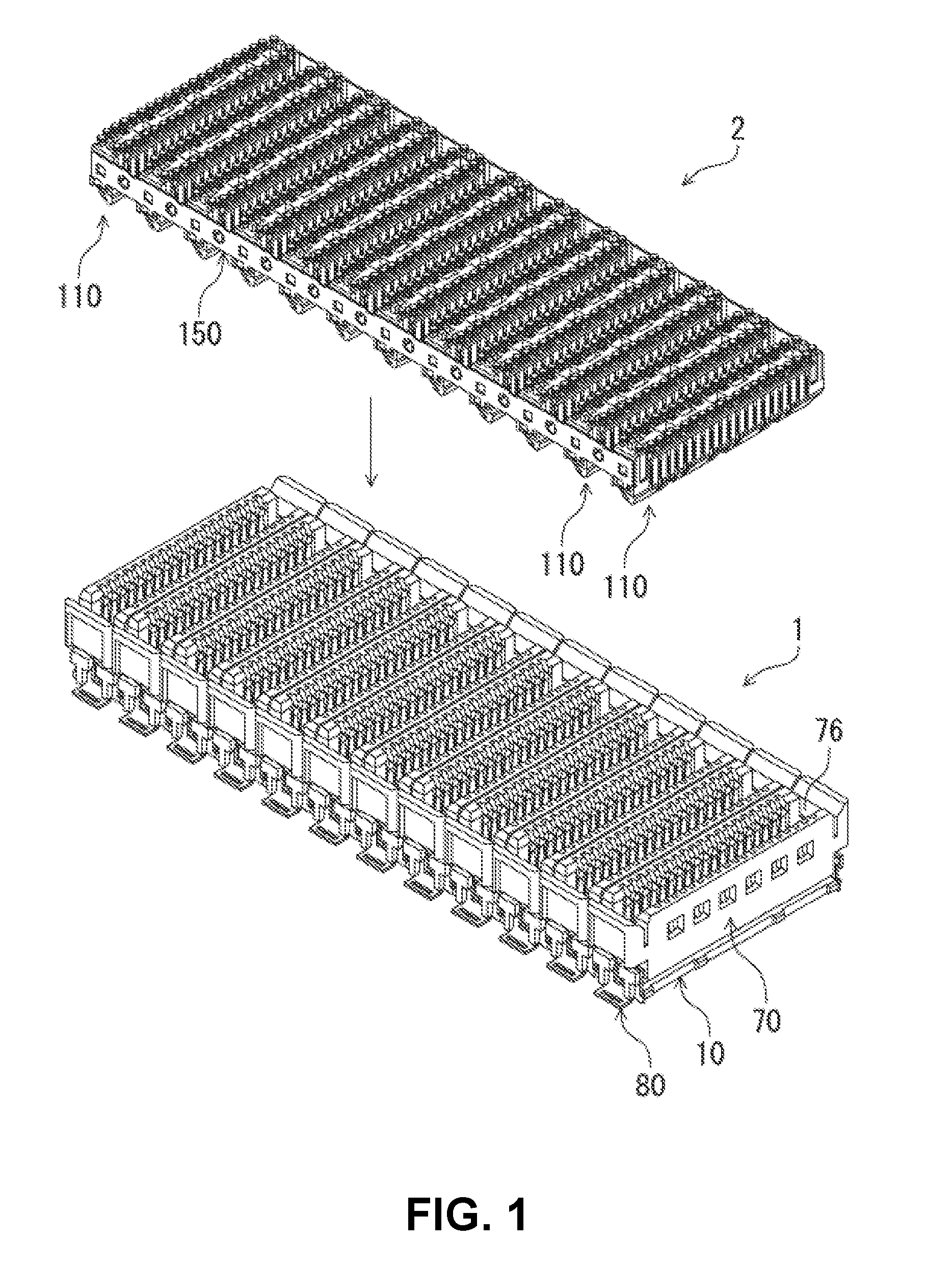
[0045]FIG. 1 is a perspective view of an electrical connector assembled component according to an embodiment of the invention, which shows a state before fitting connectors; According to the embodiment, the connector assembled component includes a receptacle connector 1 and a plug connector 2, which are fit to connect each other. The receptacle connector 1 and the plug connector 2 are electrical connectors for circuit boards, which are to be disposed on mounting surfaces of different circuit boards. The receptacle connector 1 and the plug connector 2 are fit to connect each other, having a direction perpendicular to the mounting surfaces of the respective circuit boards (an up-and-down direction in FIG. 1) as an insertion / removal direction thereof.

[0046]In the description of this embodiment below, a “connector fitting direction” is set as a direction of fitting the p...


PUM


Abstract

An electrical connector includes connecting members arranged in an arrangement direction; and a housing member for accommodating the connecting members. The connecting member includes a terminal connected to the mating connector, and a holding member for holding the terminal. The terminals includes a connecting portion at one end in a longitudinal direction for connecting to a circuit portion of the circuit board, a contact portion at the other end in the longitudinal direction for contacting with a mating contact of the mating connector, and a held portion near the connecting portion in the longitudinal direction and held with the holding member. The housing member is be movable linearly or rotatable relative to the holding member. The housing member includes a guiding surface for guiding the mating terminal. The terminal includes a deformable portion opposite to the connecting portion. The deformable portion deforms when the guiding surface guides the mating terminal.

Description

BACKGROUND OF THE INVENTION AND RELATED ART STATEMENT[0001]The present invention relates to an electrical connector for a circuit board, which is to be disposed on a mounting surface of a circuit board.[0002]In a conventional electrical connector for a circuit board (hereinafter also simply referred to as a connector), so-called a floating configuration may be employed. With the floating configuration, even when the conventional electrical connector is displaced from a normal fitting position for fitting to a mating connector in a direction parallel to the mounting surface of the circuit board, terminals of the conventional electrical connector are able to deform in the displacement direction to absorb the displacement. Therefore, it is achievable to fit and connect the conventional electrical connector to the mating connector.[0003]For example, Patent Reference has disclosed a conventional connector that can float in one direction (lateral direction) that is horizontal to the mount...

Claims


Application Information

Patent Timeline
Patent Type & Authority Patents(United States)
IPC IPC(8): H01R12/91H01R24/60
CPCH01R24/60H01R12/71H01R12/91H01R12/716H01R13/6473
Inventor TAMAI, NOBUHIRO
Owner HIROSE ELECTRIC GROUP
Why Eureka
Try Eureka