Electrical connector

a technology of electrical connectors and connectors, applied in the direction of coupling devices, two-part coupling devices, electrical apparatus, etc., can solve the problems of complex terminal shapes, less flexibility in design, and complex terminal shapes, and achieve the effect of not making the shapes of the terminals complicated, large floating, and large misalignment between the connectors

Active Publication Date: 2016-06-16
HIROSE ELECTRIC GROUP
View PDF5 Cites 13 Cited by
  • Summary
  • Abstract
  • Description
  • Claims
  • Application Information

AI Technical Summary

Benefits of technology

[0030]Therefore, even when there is misalignment between connectors in the arrangement direction of the connecting members in a connector fitting process or in a connector fitted state, the connectors can float by tilting displacement of the terminals with the deformable portions bei

Problems solved by technology

As a result, there is less flexibility in the design, and it is not preferred.
Moreover, the terminals are bent to the 90-degree rotated S-shapes, and thereby the terminals have complicated shapes.
The complicated shapes of the terminals increase the cost and l

Method used


Image

  • Electrical connector
  • Electrical connector
  • Electrical connector

Examples


Embodiment Construction

[0044]Hereunder, an embodiment of the present invention will be described with reference to the accompanying drawings.

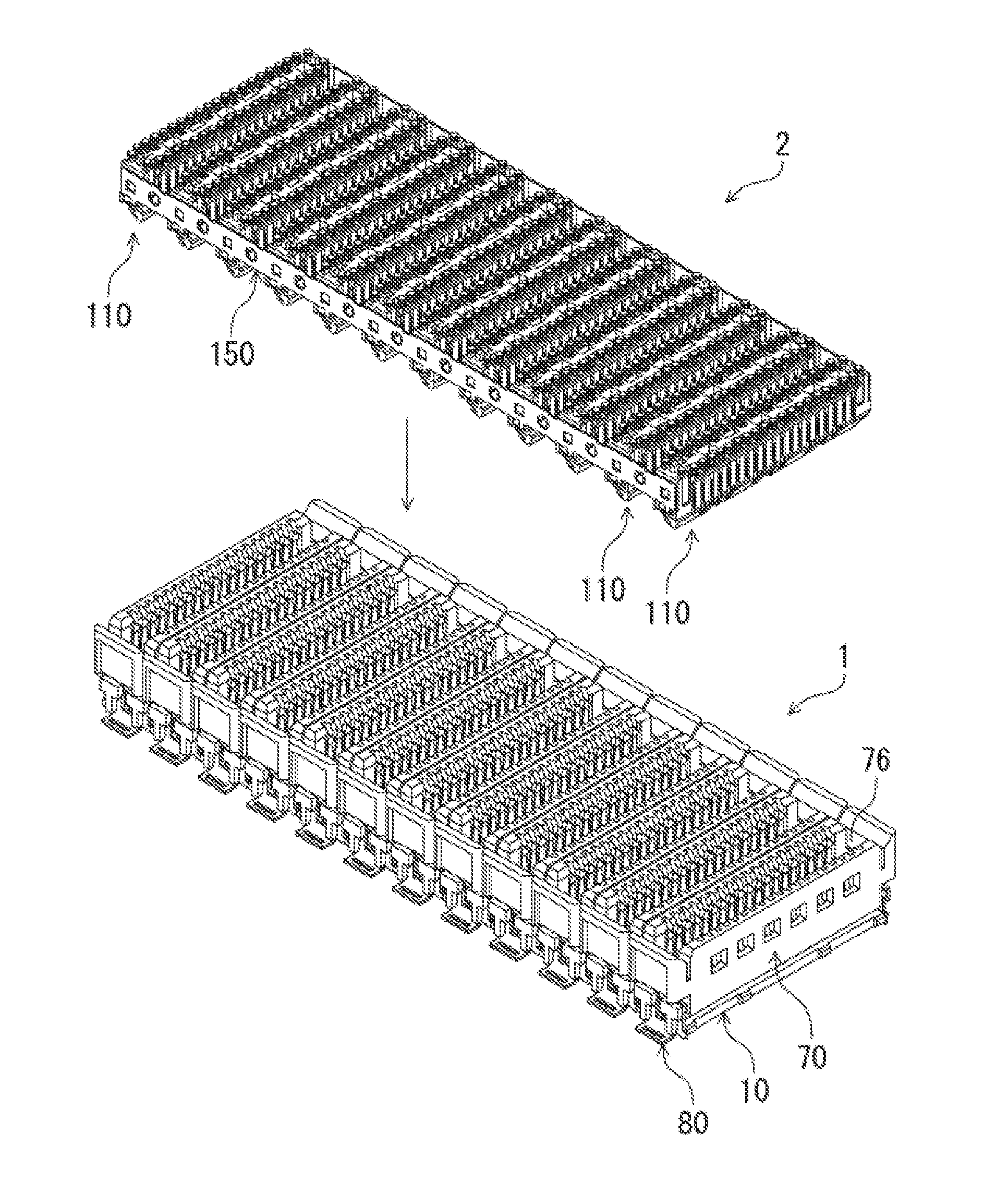
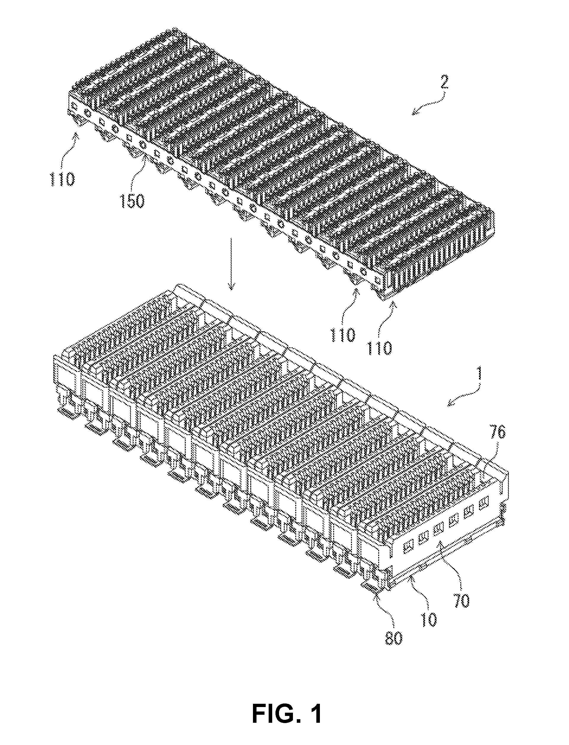
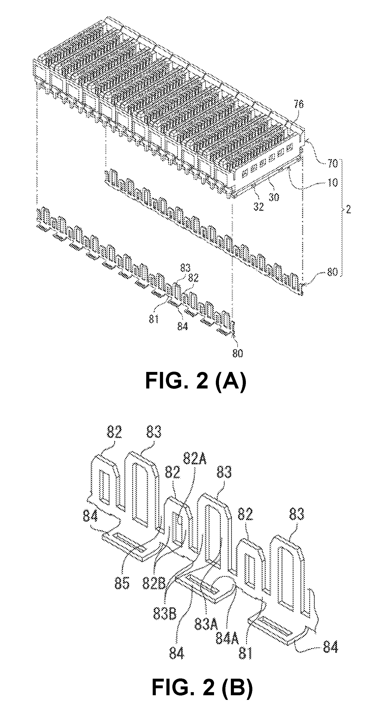
[0045]FIG. 1 is a perspective view of an electrical connector assembled component according to an embodiment of the invention, which shows a state before fitting connectors; According to the embodiment, the connector assembled component includes a receptacle connector 1 and a plug connector 2, which are fit to connect each other. The receptacle connector 1 and the plug connector 2 are electrical connectors for circuit boards, which are to be disposed on mounting surfaces of different circuit boards. The receptacle connector 1 and the plug connector 2 are fit to connect each other, having a direction perpendicular to the mounting surfaces of the respective circuit boards (an up-and-down direction in FIG. 1) as an insertion / removal direction thereof.

[0046]In the description of this embodiment below, a “connector fitting direction” is set as a direction of fitting the p...


PUM


Abstract

An electrical connector includes connecting members arranged in an arrangement direction; and a housing member for accommodating the connecting members. The connecting member includes a terminal connected to the mating connector, and a holding member for holding the terminal. The terminals includes a connecting portion at one end in a longitudinal direction for connecting to a circuit portion of the circuit board, a contact portion at the other end in the longitudinal direction for contacting with a mating contact of the mating connector, and a held portion near the connecting portion in the longitudinal direction and held with the holding member. The housing member is be movable linearly or rotatable relative to the holding member. The housing member includes a guiding surface for guiding the mating terminal. The terminal includes a deformable portion opposite to the connecting portion. The deformable portion deforms when the guiding surface guides the mating terminal.

Description

BACKGROUND OF THE INVENTION AND RELATED ART STATEMENT[0001]The present invention relates to an electrical connector for a circuit board, which is to be disposed on a mounting surface of a circuit board.[0002]In a conventional electrical connector for a circuit board (hereinafter also simply referred to as a connector), so-called a floating configuration may be employed. With the floating configuration, even when the conventional electrical connector is displaced from a normal fitting position for fitting to a mating connector in a direction parallel to the mounting surface of the circuit board, terminals of the conventional electrical connector are able to deform in the displacement direction to absorb the displacement. Therefore, it is achievable to fit and connect the conventional electrical connector to the mating connector.[0003]For example, Patent Reference has disclosed a conventional connector that can float in one direction (lateral direction) that is horizontal to the mount...

Claims


Application Information

Patent Timeline
IPC IPC(8): H01R24/60
CPCH01R24/60H01R12/71H01R12/91H01R12/716H01R13/6473
Inventor TAMAI, NOBUHIRO
Owner HIROSE ELECTRIC GROUP
Why Eureka
Try Eureka