Seal for a plug-in connection

a plug-in connection and seal technology, applied in the direction of hose connection, fluid pressure sealing joint, sleeve/socket joint, etc., can solve the problems of inadequate production of joint joints and no longer guaranteed sealing connections

Inactive Publication Date: 2002-09-24
ZF FRIEDRICHSHAFEN AG
View PDF18 Cites 76 Cited by
  • Summary
  • Abstract
  • Description
  • Claims
  • Application Information

AI Technical Summary

Benefits of technology

In contrast to the above described prior art device, an elastomeric seal according to the present invention for sealing the pipe in a push-in part of a plug-in coupling relative to a cylindrical interior surface of a housing of that plug-in coupling is sealed by a positive-fitting joint connection that connects the elastomeric seal to the push-in part. An annular molding on the elastomeric seal is no longer drawn from the outside via a collar but snap-fitted from inside into an annular groove. As a result of the insertion of a pipe in the push-in part, the joint connection between the elastomeric seal and the push-in part is locked in that the annular molding of the elastomeric seal can no longer be pulled out from its annular groove because the exterior surface of the pipe prevents the radial inward movement of the annular molding. Accordingly, frequent actuation of the plug-in connection does not cause the elastomeric seal to be released from the push-in part. To improve this connection, the planning of the diameter relationships on a web-shaped connection in the annular molding and on the internal diameter of the collar interacting with the web-shaped connection may be sized to achieve a compression of the web-shaped connection whereby the above-mentioned locking is further improved.

Problems solved by technology

When reassembly is attempted, the joint union is no longer adequately produced and a sealed connection is no longer guaranteed.

Method used


Image

  • Seal for a plug-in connection
  • Seal for a plug-in connection
  • Seal for a plug-in connection

Examples


Embodiment Construction

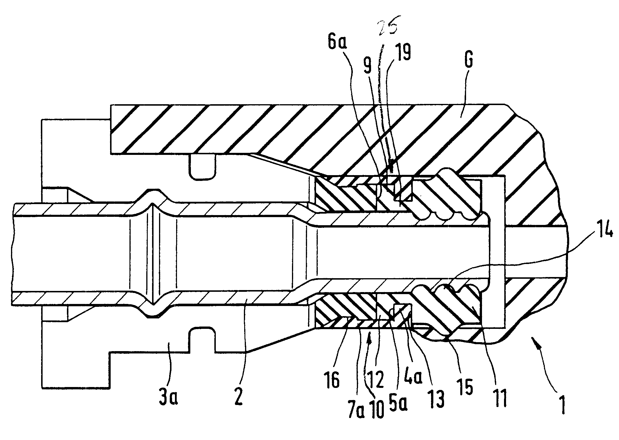
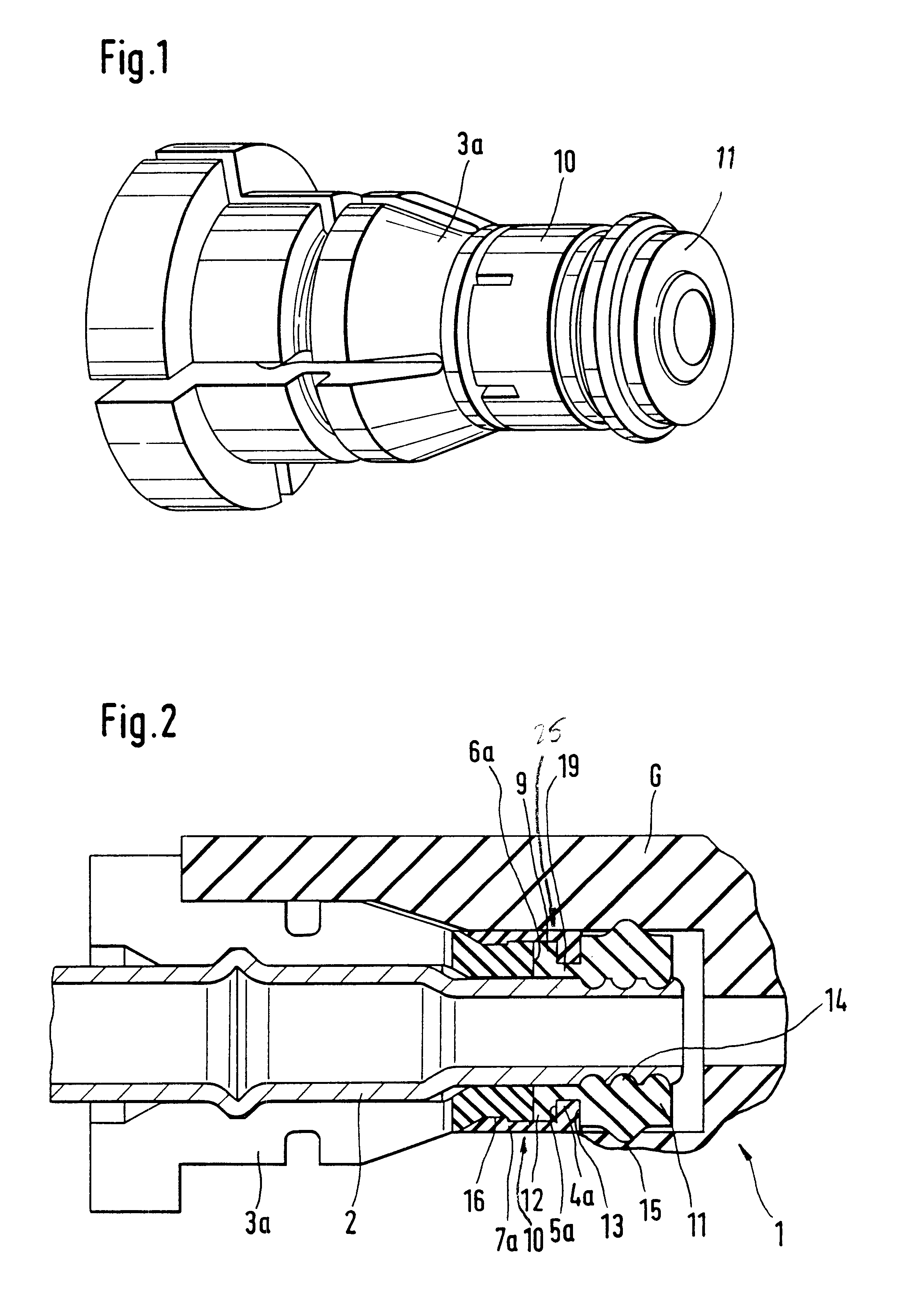
FIG. 2 shows a plug-in coupling 1 for sealing a pipe 2 in a housing G. Referring also to FIG. 1, the end of the pipe 2 lies in a push-in part 3a to which an elastomeric seal 11 is connected to seal the pipe 2 relative to an interior surface of the housing G. The push-in part 3a, the elastomeric seal 11 and the pipe 2 thus form an assembly which is pushed, i.e. inserted, into the housing G to seal the pipe 2. The elastomeric seal 11 has a radial outward-facing annular lip 15 on its radial outer surface which is under prestress with the interior surface of a drilled hole in the housing G and an annular sealing lip 14 facing radially inward and lying on the radial interior surface of the elastomeric seal 11 under prestress with an exterior surface of the pipe 2. The elastomeric seal 11 is thus pressed into an annular gap on the exterior of the pipe 2 with elastic distortion to facilitate sealing of this annular gap.

On an axial side of the elastomeric seal 11 facing the push-in part 3a,...


PUM


Abstract

An elastomeric seal seals a pipe which is held in a push-in part of a plug-in coupling relative to a cylindrical interior surface of a housing of the plug-in coupling, into which the push-in part is pushed together with the pipe. The seal is in prestressed contact with the interior surface of the housing via an outward-facing annular lip and with the pipe via a radially inward-facing annular lip. The elastomeric seal is connectable by positive fitting to the push-in part, this positive fit being lockable by the assembly of the pipe to form a non-releasable connection, the pipe having a cylindrical and uninterrupted exterior circumference in the region of the seal. The joint between the seal and the push-in part is simple to assemble and is lockable by the insertion of the pipe. The connection of the seal to the push-in part may be additionally secured, with certain changes of diameter, by compression of the web-shaped connection between them.

Description

1. Field of the InventionThe present invention relates to an elastomeric seal for sealing a pipe relative to a cylindrical inner surface of a housing in a plug-in coupling. More specifically, the present invention relates to a seal for sealing a pipe that is held in a push-in part of a plug-in coupling relative to the cylindrical inner surface of the housing of the plug-in coupling.2. Description of the Related ArtA prior art elastic seal for a hydraulic plug-in connection is disclosed in German reference DE 197 14 801 C1. This prior art seal includes a shaped profile on an interior circumferential surface which engages a shaped profile formed on the exterior circumferential surface of the sleeve with a positive fitting to secure the sealing member to the sleeve. At least one exterior sealing lip is formed on the exterior circumferential surface axially in the region of the shaped profile. In the assembled state of the plug-in connection, the exterior sealing lip is in contact with ...

Claims


Application Information

Patent Timeline
Patent Type & Authority Patents(United States)
IPC IPC(8): F16L37/02F16L37/00F16L37/04
CPCF16L37/02F16L37/088Y10S285/921F16L37/144
Inventor GROSSPIETSCH, WOLFGANGPAGELS, OLAFOTTO, MARTINSTAMPF, VOLKERRIESS, THOMASGEBAUER, DIETEREBERT, ANGELIKA
Owner ZF FRIEDRICHSHAFEN AG
Why Eureka
Try Eureka