Self-alignment magnetic connector reduced in size
a self-aligning, magnetic connector technology, applied in the direction of coupling device connection, engagement/disengagement of coupling parts, printed circuit aspects, etc., can solve the problems of increasing the size of the connector, requiring a smaller size of the recent connector, and achieving the effect of reducing the siz
- Summary
- Abstract
- Description
- Claims
- Application Information
AI Technical Summary
Benefits of technology
Problems solved by technology
Method used
Image
Examples
first embodiment
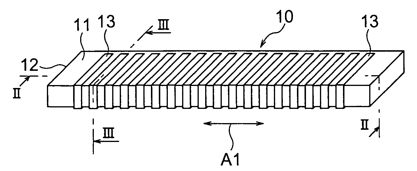
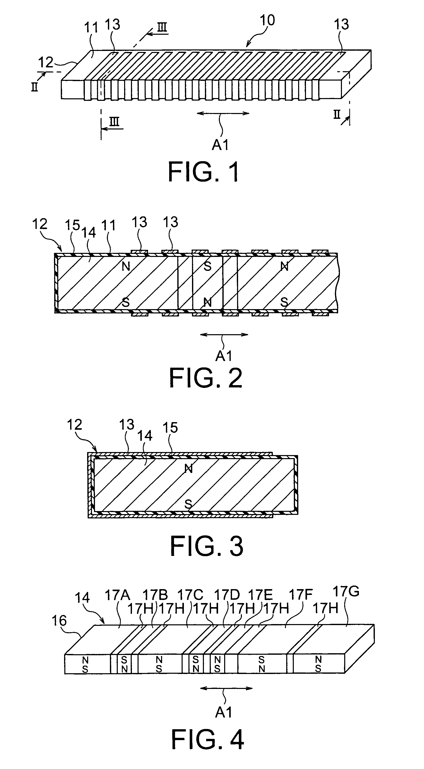
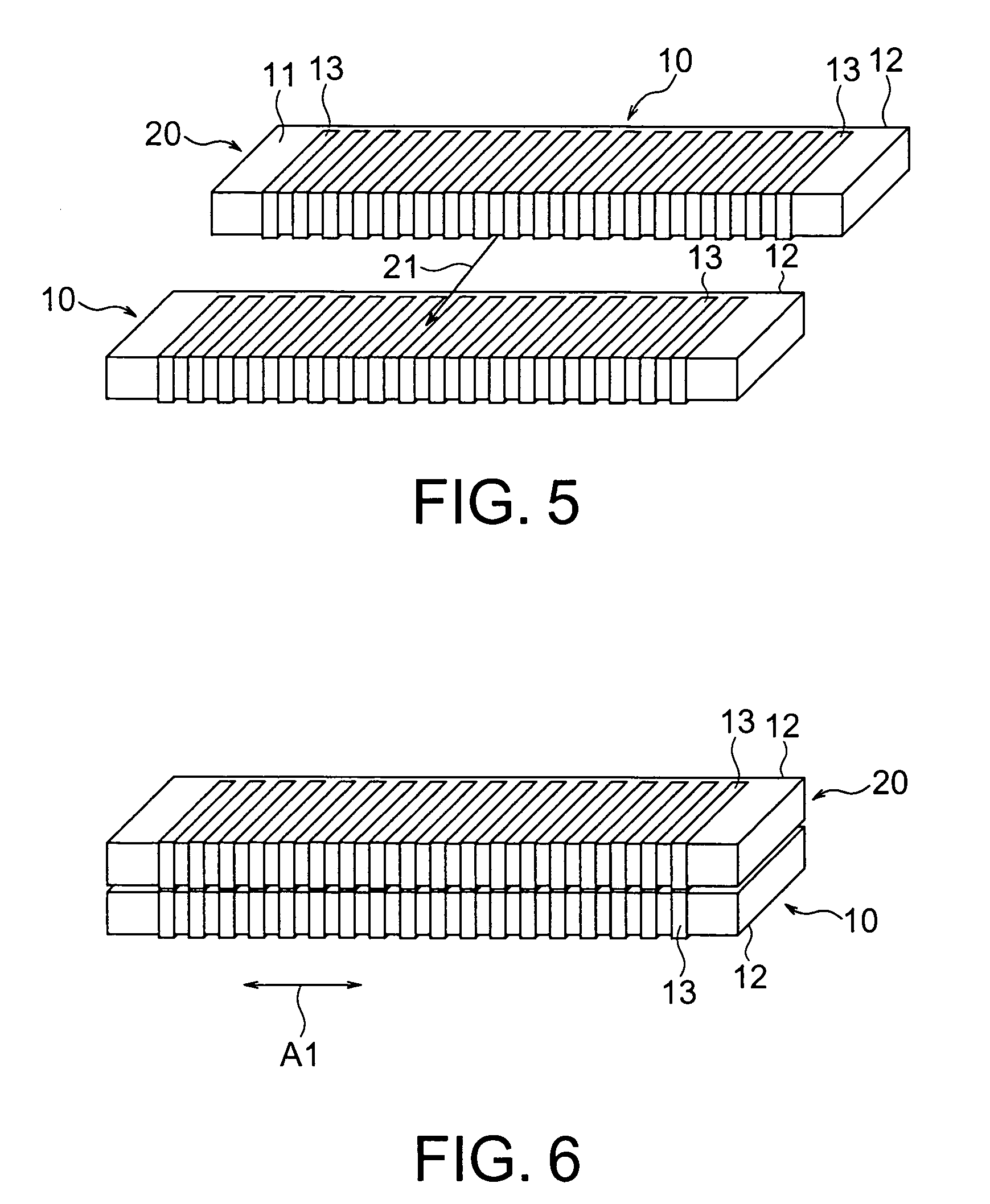
[0034]At first referring to FIGS. 1 to 3, description will be made of a magnetic connector according to this invention.
[0035]The magnetic connector 10 illustrated in the figures acquires connection with a mating connector (not shown) by magnetic attractive force. The magnetic connector 10 comprises a base member 12 having a particular surface 11 as a flat surface to be faced to the mating connector upon acquiring connection, and a plurality of conductive electrode terminals 13 fixed to the base member 12 at a predetermined pitch to be electrically connected to the mating connector. The base member 12 has a magnetic force generating portion 14 for generating magnetic force, and an elastic insulating layer 15 connected to the magnetic force generating portion 14 and defining the particular surface 11. The magnetic force generating portion 14 has different magnetic poles, i.e., N and S poles, alternately arranged along the particular surface 11 in a predetermined direction A1.
[0036]Eac...
second embodiment
[0045]Referring to FIGS. 7 through 9, a magnetic connector according to this invention will be described. Similar parts are designated by like reference numerals and description thereof will be omitted.
[0046]In each of the connector 10 and the mating connector 20 illustrated in the figures, the N and the S poles of the magnetic force generating portion 14 are formed by a plurality of, i.e., four permanent magnets 17A to 17D which are different in size and arranged in series in tight contact with one another. The insulating layer 15 depicted by dotted lines comprises an elastic material such as gel, elastomer, or polyamide fiber. In FIGS. 8 and 9, an N pole side of each magnet is hatched so as to distinguish the polarity.
[0047]One of the two magnetic force generating portions 14 illustrated in FIG. 8 is used in the connector 10 while the other is used in the mating connector 20. The permanent magnets 17A to 17D of these magnetic force generating portions 14 are designed to be reverse...
third embodiment
[0048]Referring to FIG. 10, description will be made of a magnetic connector according to this invention. Similar parts are designated by like reference numerals and description thereof will be omitted.
[0049]The connector illustrated in the figure includes a cohesive layer or a first layer 22 between the magnetic force generating portion 14 and the electrode terminals 13 as thin film electrodes. The permanent magnets 17A to 17D are adhered to a lower surface of the first layer 22. The electrode terminals 13 are adhered to the particular surface 11 defined by an upper surface of the cohesive layer 22. As the first layer 22, gel is used. The magnetic force generating portion 14 has a lower surface with the insulating layer 15 formed thereon.
PUM
 Abstract
Description
Claims
Application Information
 - R&D
- Intellectual Property
- Life Sciences
- Materials
- Tech Scout
- Unparalleled Data Quality
- Higher Quality Content
- 60% Fewer Hallucinations
Browse by: Latest US Patents, China's latest patents, Technical Efficacy Thesaurus, Application Domain, Technology Topic, Popular Technical Reports.
© 2025 PatSnap. All rights reserved.Legal|Privacy policy|Modern Slavery Act Transparency Statement|Sitemap|About US| Contact US: help@patsnap.com


