ECP/triple valve transition plate

a transition plate and triple valve technology, applied in the direction of braking systems, braking components, transportation and packaging, etc., can solve the problems of incompatibility of aem units having ecp functionality, inability to directly interface with existing triple valve equipment, and inability to support ecp functionality of triple valve equipmen

Active Publication Date: 2016-11-01
WABTEC HLDG CORP
View PDF20 Cites 4 Cited by
  • Summary
  • Abstract
  • Description
  • Claims
  • Application Information

AI Technical Summary

Benefits of technology

[0010]According to one embodiment, a transition plate provides the appropriate air-connections between an existing Triple Valve equipped railcar and an ECP stand-alone AEM. The transition plate provides an efficient application, with minimal configuration change, of an AEM to existing Triple Valve brake equipment.

Problems solved by technology

Triple Valve equipment does not currently support Electronically Controlled Pneumatic (ECP) functionality and must, instead, be pneumatically controlled.
However, AEM units having ECP functionality are not compatible and cannot directly interface with existing Triple Valve equipment due to the slight differences in construction and functionality between the current ECP and Triple Valve systems.

Method used


Image

  • ECP/triple valve transition plate
  • ECP/triple valve transition plate
  • ECP/triple valve transition plate

Examples


Embodiment Construction

[0032]For purposes of the description hereinafter, spatial orientation terms, as used, shall relate to the referenced embodiment as it is oriented in the accompanying drawing figures or otherwise described in the following detailed description. However, it is to be understood that the embodiments described hereinafter may assume many alternative variations and configurations. It is also to be understood that the specific components, devices, and features illustrated in the accompanying drawing figures and described herein are simply exemplary and should not be considered as limiting.

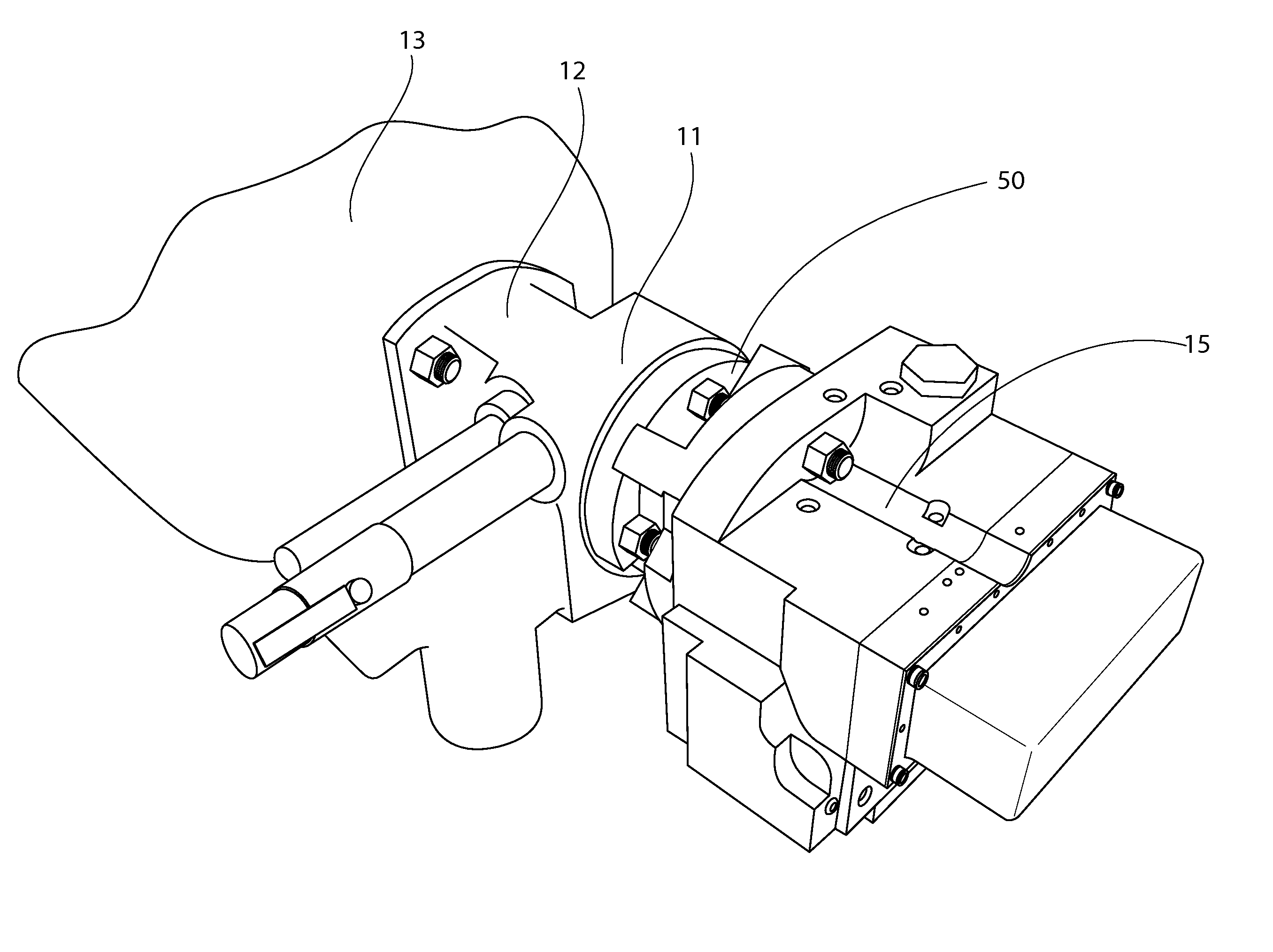
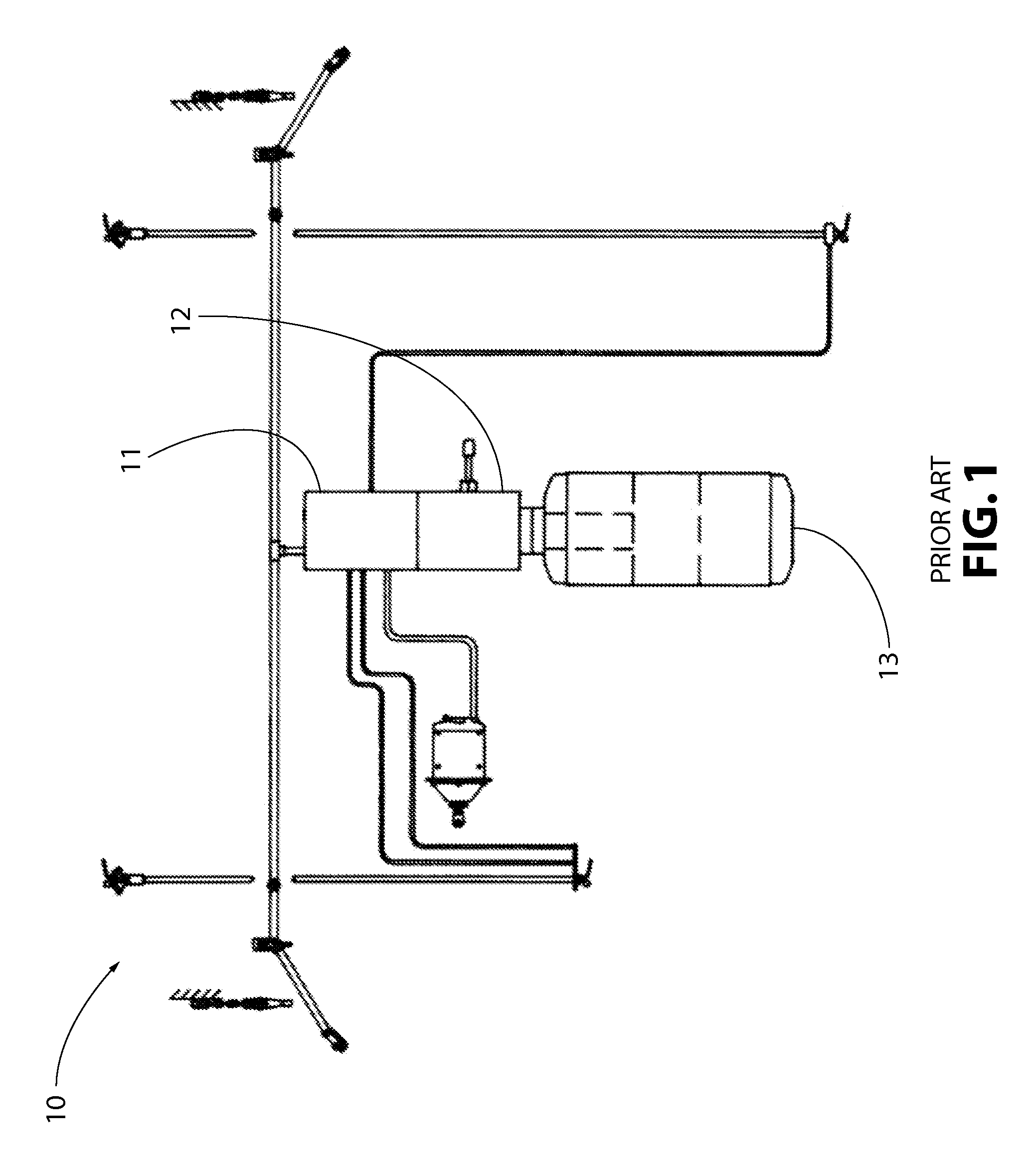
[0033]FIG. 1 illustrates a typical prior art brake system 10 for a single railway freight car according to the Triple Valve brake equipment specification in accordance with the ROA Manual, Section 7-Freight Vehicle Brakes and Brake Equipment. The brake system 10 includes a pipe mounting bracket 11 having various pipes attached thereto for establishing a pneumatic connection between the various components...


PUM

PropertyMeasurementUnit
lengthaaaaaaaaaa
pressuresaaaaaaaaaa
pressureaaaaaaaaaa

Abstract

A transition plate connects an electronic manifold to a pipe mounting bracket of a railway brake system and includes a body having a manifold portion that defines a face configured to engage the manifold and a pipe bracket portion that defines a face configured to engage the pipe mounting bracket; ports defined in the manifold face that are configured to align and communicate with ports in the face of the manifold; ports defined in the pipe bracket face that are configured to align and communicate with ports in the face of the pipe mounting bracket; and a plurality of air passages extending through the body for connecting the plurality of ports defined in the manifold face with the plurality of ports defined in the pipe bracket face. The transition plate establishes a pneumatic interface between the electronic manifold and the pipe mounting bracket.

Description

CROSS REFERENCE TO RELATED APPLICATION[0001]The present application claims priority from U.S. Provisional Patent Application No. 61 / 682,548, filed on Aug. 13, 2012, which is incorporated herein by reference in its entirety.BACKGROUND OF THE INVENTION[0002]1. Field of the Invention[0003]The present invention relates to a brake apparatus for railway vehicles and, more particularly, to a transition plate to accommodate the application of a stand-alone ECP All Electric Manifold (AEM) to an existing Triple Valve brake system.[0004]2. Description of Related Art[0005]Railways of Australia has a standardized pneumatic air brake valve control system, known as a Triple Valve system, which is similar in overall operation to American Association of Railroads (AAR) pneumatic air brake valves (such as the WABCO ABDX), with a pipe bracket, a control valve unit, and a combined reservoir.[0006]Triple Valve equipment does not currently support Electronically Controlled Pneumatic (ECP) functionality a...

Claims


Application Information

Patent Timeline
Patent Type & Authority Patents(United States)
IPC IPC(8): B60T13/66B60T17/04
CPCB60T17/043B60T13/665B60T17/04Y10T29/49826
Inventor WHITE, WARRENGAUGHAN, EDWARD W.POTTER, WILLIAM JOHNSICH, GARY M.
Owner WABTEC HLDG CORP
Why Eureka
Try Eureka