Smart plug system and method

a plug system and plug technology, applied in the direction of couplings/cases, coupling device connections, coupling parts engagement/disengagement, etc., can solve the problem that smart plugs are prone to easy th

Inactive Publication Date: 2016-11-01
BOSS CONTROLS
View PDF13 Cites 11 Cited by
  • Summary
  • Abstract
  • Description
  • Claims
  • Application Information

AI Technical Summary

Problems solved by technology

However, smart plugs may be prone to easy theft, as stealing a smart plug may be as simple as unplugging it from the outlet and removing any devices plugged therein.

Method used


Image

  • Smart plug system and method
  • Smart plug system and method
  • Smart plug system and method

Examples


Embodiment Construction

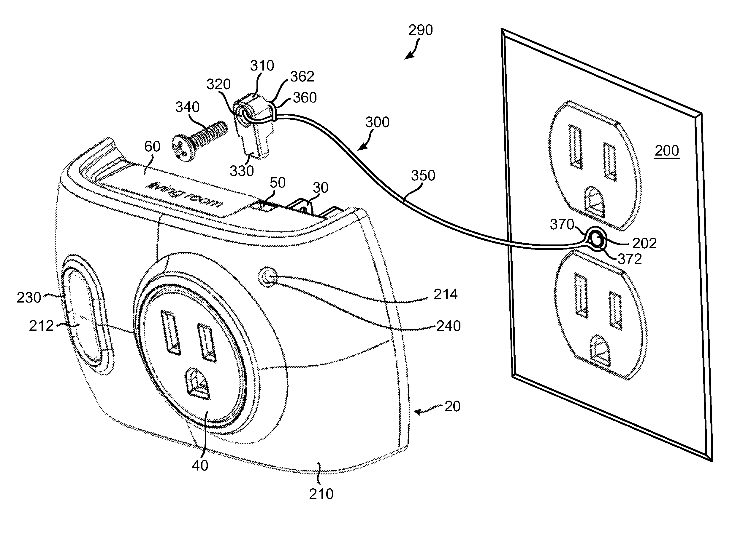
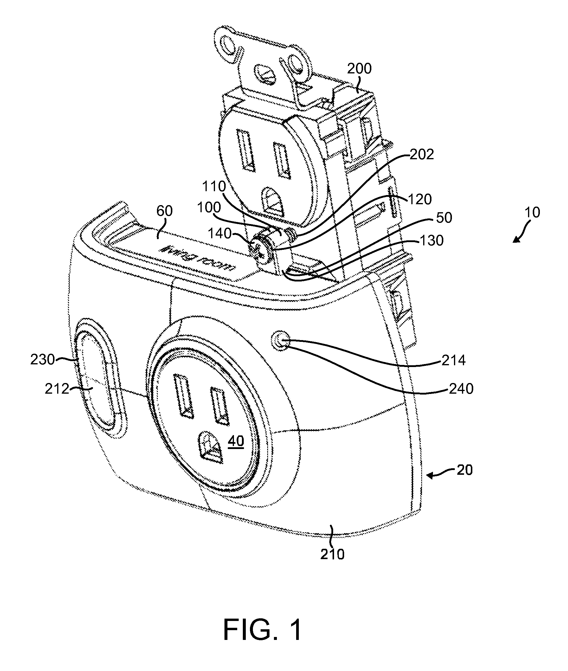
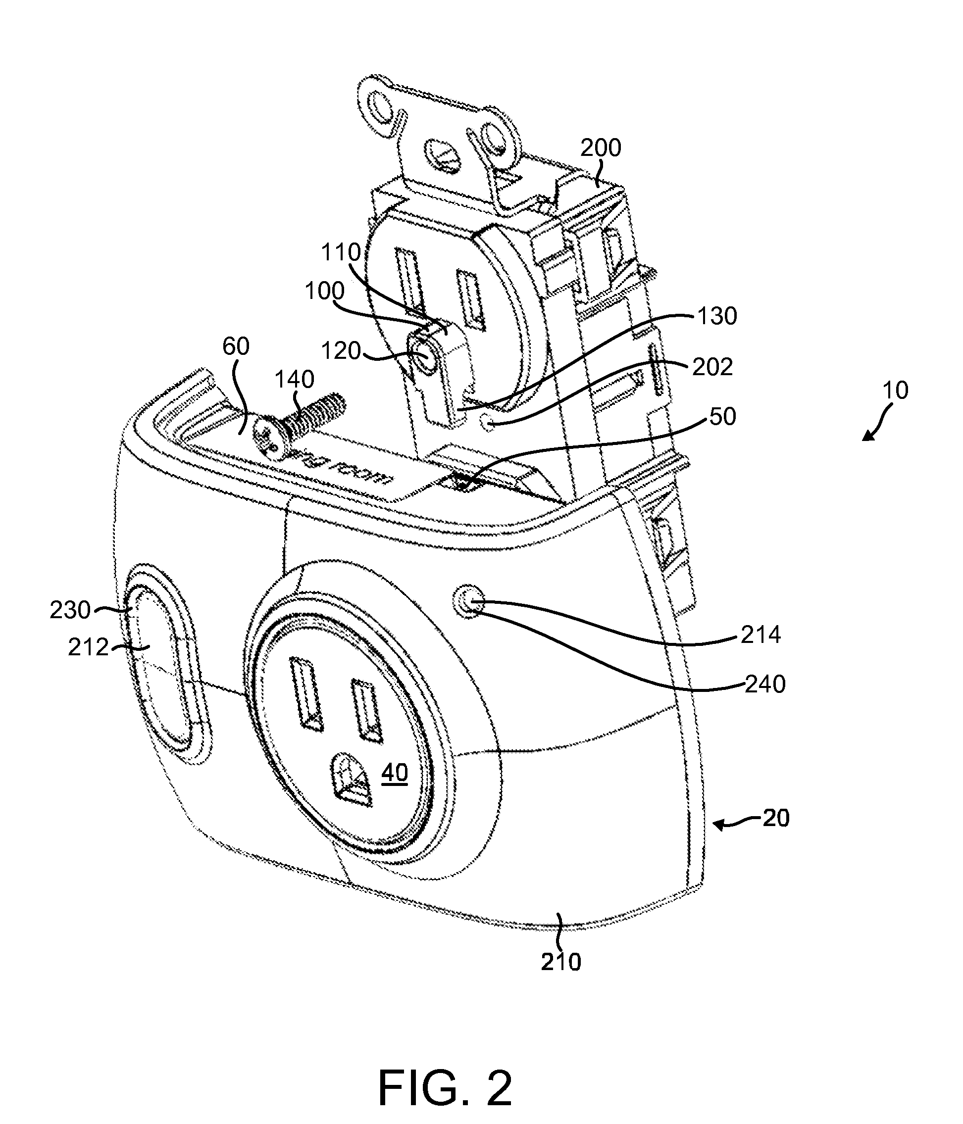
[0023]Reference will now be made to embodiments of smart plug systems and methods, examples of which are illustrated in the accompanying drawings. Details, features, and advantages of smart plug systems and methods therefore will become further apparent in the following detailed description of embodiments thereof.

[0024]It is to be understood that the specific systems, methods, and apparatuses described in the following specification are simply exemplary embodiments of the present invention and are not to be considered as limiting.

[0025]Any reference in the specification to “one embodiment,”“a certain embodiment,” or a similar reference to an embodiment is intended to indicate that a particular feature, structure or characteristic described in connection with the embodiment is included in at least one embodiment of the invention. The appearances of such terms in various places in the specification do not necessarily all refer to the same embodiment. References to “or” are furthermore...


PUM

PropertyMeasurementUnit
poweraaaaaaaaaa
energyaaaaaaaaaa
structureaaaaaaaaaa

Abstract

A smart plug system includes, in an embodiment, a smart plug that may be securable to an electrical outlet by way of an anti-theft device. The anti-theft device may include in an embodiment: a body securable to the electrical outlet; and a protrusion that extends from the body and which may extend into an aperture of the smart plug to secure the smart plug to the electrical outlet when the smart plug is plugged into an electrical outlet. In an embodiment, the smart plug may be configured to be customizable in appearance by including a plurality of different covers that may be secured to a face of the smart plug.

Description

CROSS REFERENCE TO RELATED APPLICATION[0001]This application claims priority to U.S. provisional patent application No. 61 / 940,307,filed Feb. 14, 2014,which is incorporated herein in by reference in its entirety.FIELD OF THE INVENTION[0002]The invention relates to a smart plug system and method, and more particularly to a smart plug system and method including an anti-theft device for a smart plug. The invention also relates to a smart plug that is customizable.BACKGROUND OF THE INVENTION[0003]A smart plug is an electronic device that may be configured to plug into an electrical outlet and allow devices to be plugged into it. Through the smart plug, the power from the outlet to those devices may be remotely controlled, such as by a cell phone or other mobile device, personal computer, or other wireless or wired controller. Thus, a user may remotely turn on or off devices, schedule power to those devices, and monitor their energy use.[0004]However, smart plugs may be prone to easy th...

Claims


Application Information

Patent Timeline
Patent Type & Authority Patents(United States)
IPC IPC(8): H01R13/62H01R31/06H01R13/639H01R13/717H01R13/46
CPCH01R31/065H01R13/6397H01R13/465H01R13/717Y10T29/49117H01R13/639H01R24/68H01R43/26
Inventor PUSCHNIGG, GREG W.KRUMMEY, MIKE
Owner BOSS CONTROLS
Why Eureka
Try Eureka