Smart plug node management

a plug-in node and intelligent technology, applied in the direction of electrical equipment, instruments, transmission, etc., can solve the problems of increasing the financial and manpower costs of maintaining the rack system, not being able to locate and access the server node in a typical rack system, and adding a layer of complexity

Active Publication Date: 2017-11-02
QUANTA COMPUTER INC
View PDF8 Cites 4 Cited by
  • Summary
  • Abstract
  • Description
  • Claims
  • Application Information

AI Technical Summary

Benefits of technology

[0003]The following presents a simplified summary of one or more embodiments in order to provide a basic understanding of present technology. This summary is not an extensive overview of all contemplated embodiments of the present technology, and is intended to neither ide...

Problems solved by technology

In remote management of server nodes, locating and accessing a server node in a typical rack system may not be readily straightforward due to the large number of server nodes presen...

Method used


Image

  • Smart plug node management
  • Smart plug node management
  • Smart plug node management

Examples


Embodiment Construction

[0014]Various aspects of the present technology are described with reference to the drawings. In the following description, for purposes of explanation, numerous specific details are set forth in order to provide a thorough understanding of one or more aspects. It can be evident, however, that the present technology can be practiced without these specific details. In other instances, well-known structures and devices are shown in block diagram form in order to facilitate describing these aspects. The word “exemplary” is used herein to mean “serving as an example, instance, or illustration.” Any embodiment described herein as “exemplary” is not necessarily to be construed as preferred or advantageous over other embodiments.

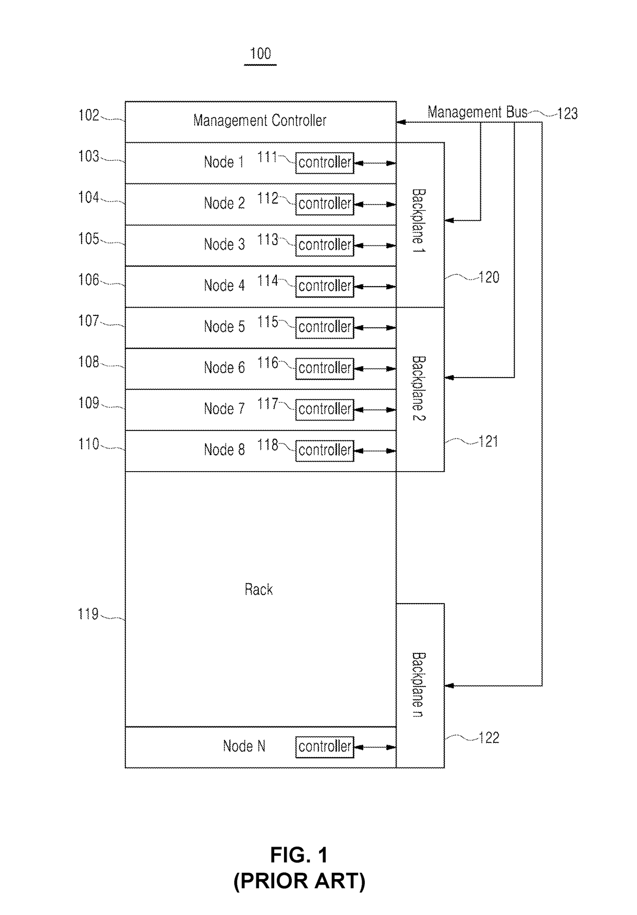
[0015]The disclosure turns first to FIG. 1, which illustrates a block diagram of exemplary embodiment of locating a server node in a traditional management backplane rack system 100. As shown in the block diagram 100, a rack system 119 is provided, which is an asse...


PUM


Abstract

In the maintenance of rack system, a computing device may implement a plurality of smart plugs and a communication bus in a system. A smart plug may be plugged into a server node for communication between a management node and a designated server node. The communication bus may be coupled to the smart plugs for transmitting I2C packets. A server node may be associated with a corresponding smart plug that includes a unique address on the communication bus. The smart plug may be configured to receive a message via the communication bus. The smart plug is configured to determine whether the request is addressed to a unique address associated with the smart plug. Upon determining that the message is addressed to the unique address, the smart plug may reformat the request compatible with server node port using the local address. Reformatting request may depend on types of server node ports.

Description

TECHNICAL FIELD[0001]This application relates to managing a server node, and more particularly to communicating with a server node using a smart plug device.BACKGROUND[0002]In remote management of server nodes, locating and accessing a server node in a typical rack system may not be readily straightforward due to the large number of server nodes present in typical rack systems. Thus, in some rack systems, a management backplane may be configured to locate server nodes in the rack system. The management backplane is typically a printed circuit board (PCB) that connects server nodes to the management node. Often times, the management backplane adds a layer of complexity to the rack system, increasing both financial and manpower costs for maintaining the rack system.SUMMARY OF THE INVENTION[0003]The following presents a simplified summary of one or more embodiments in order to provide a basic understanding of present technology. This summary is not an extensive overview of all contempl...

Claims


Application Information

Patent Timeline
IPC IPC(8): G06F13/40G06F13/42G06F13/38
CPCG06F13/4081G06F13/385G06F13/4282G06F13/4068G06F2213/0016H04L41/344H04L41/00G06F13/00G06F13/382
Inventor TUNG, YEN-PING
Owner QUANTA COMPUTER INC
Why Eureka
Try Eureka